Energy-saving computer room air conditioning system

A technology for computer room air conditioning and outdoor air, which is used in air conditioning systems, heating and ventilation control systems, heating and ventilation safety systems, etc. It can solve the problems of complex structure and large occupied space, achieve precise humidity and temperature control, and reduce occupied space. , the effect of reducing input costs

Active Publication Date: 2017-04-26
GREE ELECTRIC APPLIANCES INC
View PDF7 Cites 3 Cited by
  • Summary
  • Abstract
  • Description
  • Claims
  • Application Information

AI Technical Summary

Problems solved by technology

[0006] Therefore, the technical problem to be solved by the present invention is to overcome the defects of complex structure and large occupied space of the energy-saving computer room air-conditioning system in the prior art, so as to provide an energy-saving computer room air-conditioning system with simple structure and small occupied space

Method used


Image

  • Energy-saving computer room air conditioning system
  • Energy-saving computer room air conditioning system
  • Energy-saving computer room air conditioning system

Examples


Embodiment 1

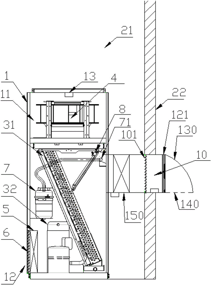
[0054] figure 1 Shown is the energy-saving machine room air conditioning system 0 in this embodiment, which includes: a casing 1, a circulation channel, an indoor part of a refrigeration mechanism and an indoor fan 4, and also includes an outdoor air intake channel 10 and a controller. The casing 1 has The inner cavity 11 and the circulation channel connecting the indoor 21 and the inner cavity 11, the air inlet 12 and the air outlet 13 of the circulation channel are arranged on the casing 1; the indoor part of the refrigeration mechanism is arranged in the inner cavity 11 The indoor fan 4 is located in the circulation channel and is installed on the casing 1. In this embodiment, the indoor fan 4 is an EC centrifugal fan arranged at the air outlet 13 of the circulation channel, namely The motor of the centrifugal fan is a three-phase AC permanent magnet synchronous motor; the outdoor air inlet channel 10 is arranged on the casing 1 and communicates with the outdoor and the inn...

Embodiment 2

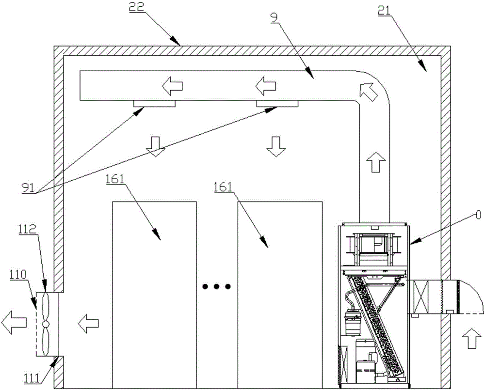
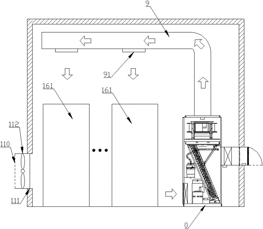
[0080] In this embodiment, on the basis of the above-mentioned Embodiment 1, the arrangement of the exhaust pipe 9 is replaced by connecting one end of the exhaust pipe 9 with the air outlet 13 of the circulation channel provided on the upper part of the housing 1, The other end extends to the bottom of the equipment room 161 and is connected to the casing of the equipment room 161, that is, the exhaust hole 91 of the exhaust pipe 9 directly faces the lower part of the equipment room 161 to exhaust air, the cold air flows from the bottom to the top, and the hot air of the equipment room 161 is exhausted. is pushed up by the cold wind, and cooled from the inside of the equipment 161 in the equipment room, and the cooling effect is good, such as Figure 4 and Figure 5 As shown, in order to be more conducive to the discharge of air, the exhaust fan 112 can be arranged at a position close to the ceiling to form an up-and-down convection manner.

[0081] In this embodiment, the o...


PUM


Abstract

The invention relates to the field of air conditioners, in particular to an energy-saving computer room air conditioning system which comprises a shell, a refrigeration mechanism indoor part, an indoor fan, an outdoor air inlet channel and a controller. The outdoor air inlet channel is formed in the shell and communicates with the outside and an inner cavity. The controller controls leading and disconnecting between the outdoor air inlet channel and the inner cavity as well as between a cyclic channel and the inner cavity. When the outdoor air inlet channel is opened, the cyclic channel is closed; and when the outdoor air inlet channel is closed, the cyclic channel is opened. The energy-saving computer room air conditioning system is simple in structure and small in occupied space, and the defects that in the prior art, energy-saving computer room air conditioning systems are complex in structure and large in occupied space are overcome.

Description

technical field [0001] The invention relates to the field of air conditioners, in particular to an energy-saving machine room air conditioner system. Background technique [0002] With global warming, energy is constantly in short supply, and people's demand for and dependence on energy is getting stronger and stronger, making energy-saving technology more and more important. [0003] With the development of network communication technology, the number of electronic computer rooms has gradually increased. Due to the relatively large heat load of the current computer rooms, cooling is required throughout the year. Even in winter, the computer room air conditioners are in a state of cooling and humidification. Therefore, the air-conditioning equipment installed in the equipment room has to run for a long time, which consumes a lot of power. [0004] In the prior art, many energy-saving technologies for equipment rooms mainly save energy through the temperature difference betw...

Claims


Application Information

Patent Timeline
Patent Type & Authority Applications(China)
IPC IPC(8): F24F5/00F24F11/00F24F13/28
CPCF24F5/001F24F5/0046F24F11/30F24F11/62F24F13/28F24F2110/10F24F2110/20F24F11/65
Inventor 刘警生路文博范兴发苏培焕王芳周鸣宇
Owner GREE ELECTRIC APPLIANCES INC
Why Eureka
Try Eureka