Workpiece annealing device

A technology for annealing equipment and workpieces, applied in heat treatment equipment, lighting and heating equipment, furnace components, etc., can solve problems such as lack of heating capacity, unstable temperature uniformity, and blocked pipes

Inactive Publication Date: 2017-09-19
绍兴柯桥华润钢业有限公司
View PDF4 Cites 0 Cited by
  • Summary
  • Abstract
  • Description
  • Claims
  • Application Information

AI Technical Summary

Problems solved by technology

[0004] The currently used annealing equipment has the following problems before the combustion air is preheated: 1. The heating capacity of the furnace is unstable, and the temperature uniformity is unstable
The workpieces in the heating stage in the annealing furnace need to reach a certain process temperature within the specified time range. Due to the different specifications of the workpieces and the different distribution densities in the furnace, strong heating capacity and uniform stabilit...

Method used


Image

  • Workpiece annealing device

Examples


Embodiment Construction

[0015] The present invention will be described in further detail below by means of specific embodiments:

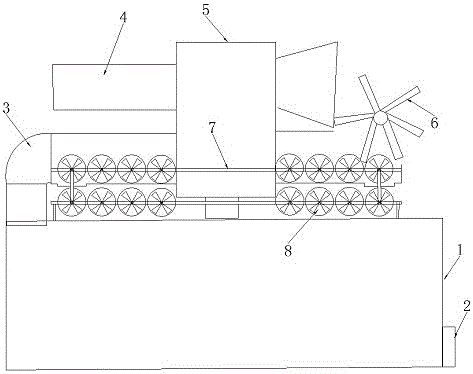
[0016] The reference signs in the drawings of the description include: furnace body 1 , air inlet 2 , smoke outlet pipe 3 , preheating pipe 4 , heat exchanger 5 , wind wheel 6 , slide rod 7 , and roller 8 .

[0017] The embodiment is basically as figure 1 Shown:

[0018] The workpiece annealing equipment of this embodiment includes a furnace body 1, a smoke outlet pipe 3 is provided on one side of the top of the furnace body 1, a heat exchanger 5 is provided in the center of the top of the furnace body 1, and the smoke outlet pipe 3 passes through the lower part of the heat exchanger 5 , The upper part of the heat exchanger 5 is provided with a preheating pipe 4, and the inlet of the preheating pipe 4 is larger than the outlet of the preheating pipe 4. Two layers of sliding rods 7 are placed on the furnace body 1, and connecting rods are arranged between the two layers ...


PUM


Abstract

The invention belongs to the field of heat treatment equipment, and particularly relates to a workpiece annealing device. The device comprises a furnace body, a smoke outlet pipe is arranged on one side of the top of the furnace body, a heat exchanger is arranged in the center of the top of the furnace body, the smoke outlet pipe penetrates the lower portion of the heat exchanger, a preheating pipe is arranged on the upper portion of the heat exchanger, two layers of sliding rods are arranged on the upper surface of the furnace body, a connecting rod is arranged between the two layers of sliding rods, the portion, located in the smoke outlet pipe, of the upper layer sliding rod is provided with multiple rollers in a head-to-tail connection manner, holes allowing the rollers to be in and be out are formed in the bottom wall of the smoke outlet pipe, an air wheel is arranged on an inlet of the preheating pipe, a blade of the air wheel stretches into the smoke outlet pipe and can push the rollers, and an outlet of the preheating pipe leads to an air inlet of the furnace body. Production capacity of the annealing furnace is improved, gas consumption is reduced, the environment-friendly needs are met, the smoke outlet pipe can be prevented from being blocked, and furnace ash stacking is avoided.

Description

technical field [0001] The invention belongs to the field of heat treatment equipment, in particular to workpiece annealing equipment. Background technique [0002] In the production process of mechanical workpiece casting, heat treatment is an important link. The heat treatment process is generally divided into four stages, namely heating section, heat preservation section, fast cooling section and slow cooling section. The function of the heating section is to cool the workpiece within a certain period of time. Heating to the temperature required by the process, entering the heat preservation section, keeping it within a stable temperature range for a certain period of time, completing the transformation from cementite to ferrite in the metallographic structure, and then entering the fast cooling section to cool the temperature rapidly , enter the slow cooling section, and complete the transformation from pearlite to ferrite at a stable cooling rate. After the workpiece u...

Claims


Application Information

Patent Timeline
IPC IPC(8): C21D9/00C21D1/26F27D17/00
CPCC21D1/26C21D9/00C21D9/0006F27D17/004
Inventor 王文革
Owner 绍兴柯桥华润钢业有限公司
Why Eureka
Try Eureka