Eureka AIR delivers breakthrough ideas for toughest innovation challenges, trusted by R&D personnel around the world.

Mechanical injection distribution machine

A mechanical and injection technology, applied in the direction of mechanical conveyors, conveyors, conveyor objects, etc., can solve the problems of not being able to adapt to labor intensity and technical operation requirements, low degree of automation, and high operational technical requirements, and achieve convenient observation equipment Operation status, improvement of automation level, and good visibility

Active Publication Date: 2017-04-26
HENAN POLYTECHNIC UNIV
View PDF8 Cites 0 Cited by
  • Summary
  • Abstract
  • Description
  • Claims
  • Application Information

AI Technical Summary

Problems solved by technology

[0002] At present, the overall automation of the injection drug production process is not high, and the injection material boxes are frequently transferred between various processes, and each process has an independent feeding process
The automatic packaging line process is an independent process. At present, when the injection automatic packaging line is operated, the injection materials are all fed manually. Pull out or push away the plug at the end of the injection material box, lift the material box to the top of the packaging machine tray, and then slowly discharge the material; in the discharging process, in order to ensure that the injection material is evenly discharged and not broken, it needs to swing left and right, labor The intensity is high and the operation technology requirements are high, especially for the feeding of large-capacity injection material boxes, ordinary workers cannot adapt to the labor intensity and technical operation requirements, so how to reduce the labor intensity of feeding materials and improve packaging efficiency is an urgent problem in the production process of injection drugs today. technical issues to be resolved

Method used


Image

  • Mechanical injection distribution machine
  • Mechanical injection distribution machine
  • Mechanical injection distribution machine

Examples


Embodiment Construction

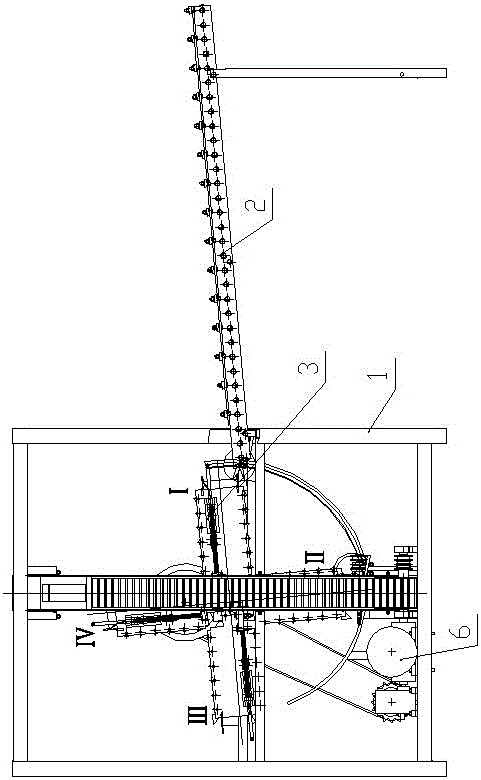
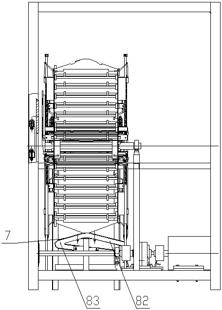
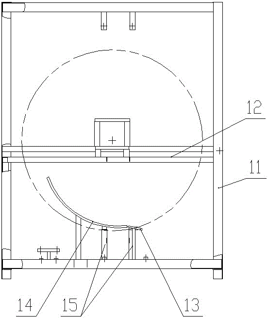
[0038] Such as Figure 1-14 As shown, the mechanical injection dispensing machine of the present invention includes a frame 1, the right side of the frame 1 is provided with a whole plate feeding mechanism 2, and the frame 1 is provided with a material box turning feeding device 3, and the bottom of the frame 1 Equipped with a power control system 6, the left side discharge part of the whole tray feeding mechanism 2 is connected with the feed part of the material box turning feeding device 3, and the discharging part of the material box turning feeding device 3 is connected with a feeding track 7 The frame 1 includes a frame 11, the frame 11 is a rectangular parallelepiped, and the middle part of the frame 11 is horizontally provided with a rectangular support beam frame 12;

[0039] The power control system 6 includes a motor 8 and a single-output worm reducer 10, the power output shaft of the motor 8 is connected to the power input shaft of the single-output worm reducer 10,...


PUM


Abstract

A mechanical injection distribution machine comprises a rack, wherein a whole plate feeding mechanism is arranged on the right side of the rack; a material box turnover feeding device is arranged in the rack; a power control system is arranged at the bottom of the rack; the left side discharging part of the whole plate feeding mechanism is connected with the feeding part of the material box turnover feeding device; the discharging part of the material box turnover feeding device is connected with a material conveying track; the rack comprises a framework which is cuboid in appearance; a rectangular support beam frame is horizontally arranged in the middle of the framework; and the power control system is in transmission connection with the material box turnover feeding device. The mechanical injection distribution machine can realize injection material box feeding and discharging and injection conveying discharging, which are all automatically finished by mechanical structures, and besides, empty material box discharge and automatic door panel control functions are also provided to realize continuous injection feeding.

Description

technical field [0001] The invention relates to a conveying and feeding machine, in particular to a mechanical injection dispenser. Background technique [0002] At present, the overall automation of the injection drug production process is not high, and the injection material boxes are frequently transferred between various processes, and each process has an independent feeding process. The automatic packaging line process is an independent process. At present, when the injection automatic packaging line is operated, the injection materials are all fed manually. Pull out or push away the plug at the end of the injection material box, lift the material box to the top of the packaging machine tray, and then slowly discharge the material; in the discharging process, in order to ensure that the injection material is evenly discharged and not broken, it needs to swing left and right, labor The intensity is high and the operation technology requirements are high, especially for ...

Claims


Application Information

Patent Timeline
IPC IPC(8): B65G37/00B65G47/248
CPCB65G37/00B65G47/248Y02W30/62
Inventor 杨现卿曹军刘瑜吴雪峰薛铜龙贾智宏张晓辉王福荣周甲伟
Owner HENAN POLYTECHNIC UNIV
Why Eureka
Eureka Blog
Learn More