Surgical stapler
A stapler and surgical technology, applied in the field of medical devices, can solve problems such as reflux, and achieve the effect of avoiding anastomotic leakage
- Summary
- Abstract
- Description
- Claims
- Application Information
AI Technical Summary
Problems solved by technology
Method used
Image
Examples
Embodiment 1
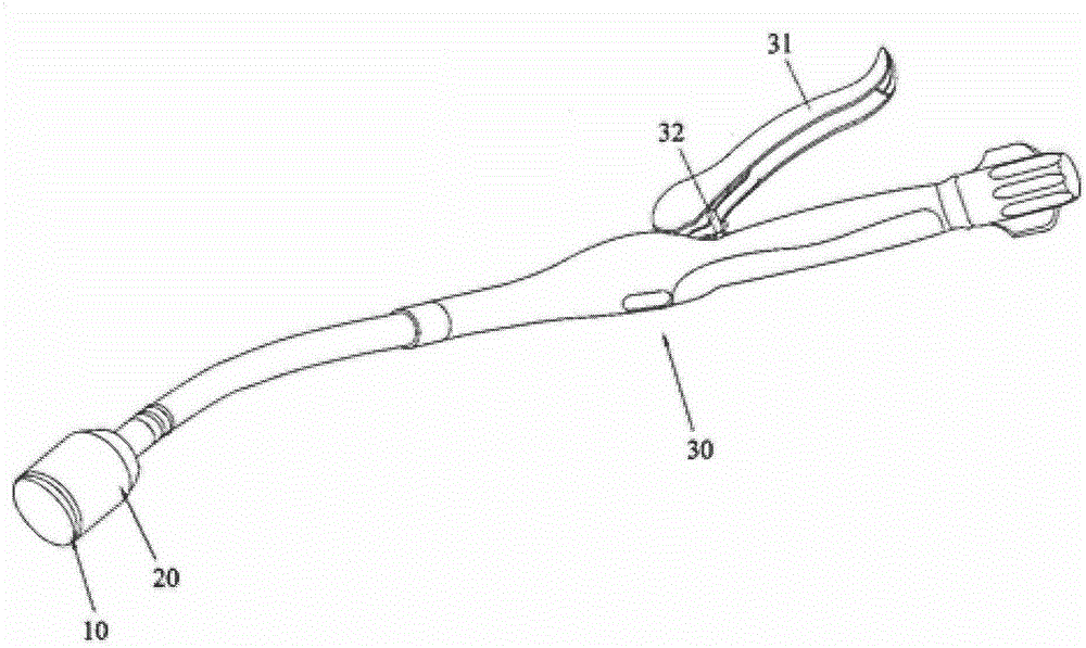
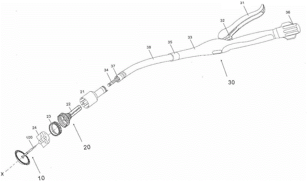
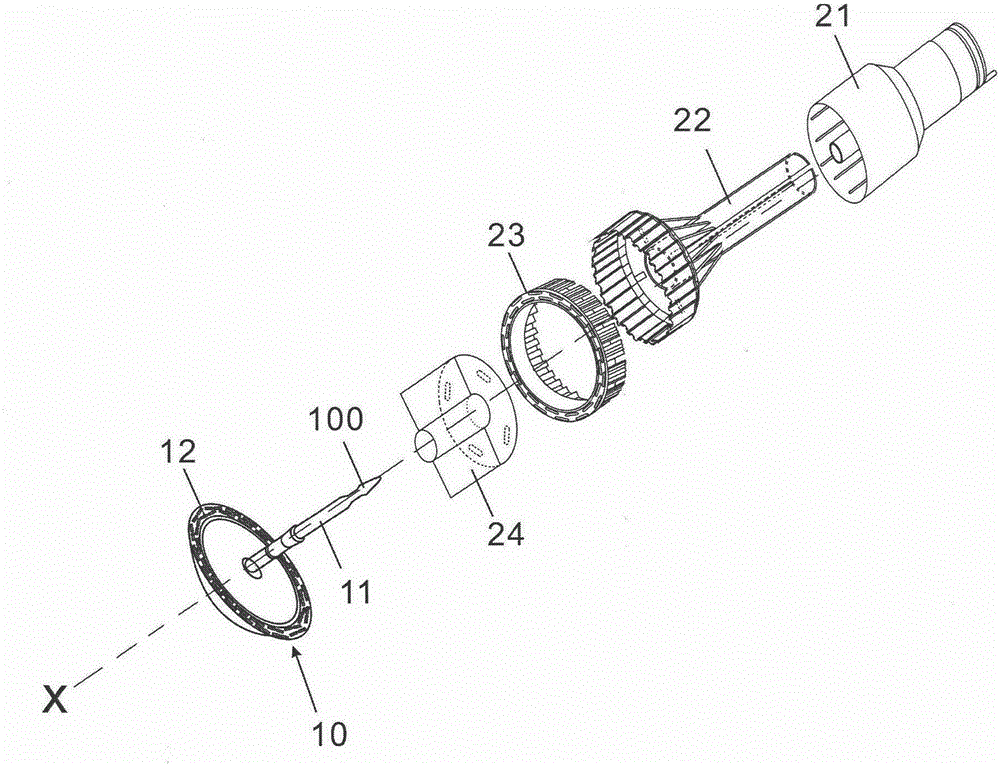
[0071] figure 1 , figure 2 The overall structure of the surgical stapler of this embodiment is shown. As shown in the figure, the surgical stapler includes three parts: an operating part 30, a head 20, and an anvil 10.
[0072] 1. Operation part 30.
[0073] Such as figure 2 As shown, the operating portion 30 includes a cylindrical shell 33, which is formed by buckling two separate shells, and a hoop 35 is used to clamp one end of the shell. A sleeve 38 is arranged inside the cavity formed by the housing 33, and a push-pull rod (not shown in the figure) is arranged inside the sleeve 38. One end of the push-pull rod is connected to the butting portion 34 for docking with the nail anvil, and the other end is connected to the knob 36; The knob 36 can control the push-pull rod to advance or retreat in the sleeve 38, thereby causing the docking portion 34 to advance or retreat. Such as figure 2 As shown, the mating portion 34 is specifically a cavity with a fastening device on the p...
Embodiment 2
[0100] Image 6 , Figure 7 The cutter in Example 2 is shown. This embodiment is different from the first embodiment in that: in this embodiment, there are three linear cutters, which are located around the hollow cylinder 213, and the linear cutter 24 includes a flat elliptical push pin support. Two linear cutters 242 in the direction of the long axis of the surface 223, one linear cutter 243 in the direction of the short axis of the flat elliptical push pin support surface 223, and the bottom 244 of the cutter. The hollow cylinder 213 has two grooves in the long axis direction of the flat elliptical push pin support surface 223. The inner side of the linear cutter 242 is stuck in the grooves, and the hollow cylinder 213 is on the flat ellipse push pin support surface 223. There is also a groove in the direction of the short axis, the inner side of the linear cutter 243 is stuck in the groove, and the linear cutter is connected to the supporting surface 223 of the push pin col...
Embodiment 3
[0102] Figure 8 , Picture 9 The cutter in Example 3 is shown. Compared with the first embodiment, this embodiment is different in that: in this embodiment, there are four linear cutters located around the hollow cylinder 213, and the linear cutter 24 includes a flat elliptical push pin support. Two linear cutters 242 in the direction of the long axis of the surface 223, two linear cutters 243 in the direction of the short axis of the flat elliptical push pin support surface 223, and the bottom 244 of the cutter. The four linear cutters are arranged in a crisscross pattern. The hollow cylinder 213 has two grooves in the long axis direction of the flat elliptical push pin support surface 223. The inner side of the linear cutter 242 is stuck in the grooves, and the hollow cylinder 213 is on the flat ellipse push pin support surface 223. There are two grooves in the short axis direction, the inner side of the linear cutter 243 is stuck in the groove, and the linear cutter is con...
PUM
 Abstract
Description
Claims
Application Information
 - R&D Engineer
- R&D Manager
- IP Professional
- Industry Leading Data Capabilities
- Powerful AI technology
- Patent DNA Extraction
Browse by: Latest US Patents, China's latest patents, Technical Efficacy Thesaurus, Application Domain, Technology Topic, Popular Technical Reports.
© 2024 PatSnap. All rights reserved.Legal|Privacy policy|Modern Slavery Act Transparency Statement|Sitemap|About US| Contact US: help@patsnap.com


