
Multi-inlet, multi-spray fluidic cup nozzle with shared interaction region and spray generation method

A technology of nozzles and inlets, applied in the field of multiple inlets with a common interaction area, multiple jet cup nozzles and jet generation, which can solve the problems of increasing cost and increasing assembly complexity

Active Publication Date: 2017-04-19
DLHBOWLES INC
View PDF16 Cites 9 Cited by
  • Summary
  • Abstract
  • Description
  • Claims
  • Application Information

AI Technical Summary

Problems solved by technology

Adding an external foaming tool is a commonly offered method for jetting consumer goods for foaming, but external foaming tools add cost and require additional parts and add complexity to assembly

Method used


Image

  • Multi-inlet, multi-spray fluidic cup nozzle with shared interaction region and spray generation method
  • Multi-inlet, multi-spray fluidic cup nozzle with shared interaction region and spray generation method
  • Multi-inlet, multi-spray fluidic cup nozzle with shared interaction region and spray generation method

Examples


Embodiment Construction

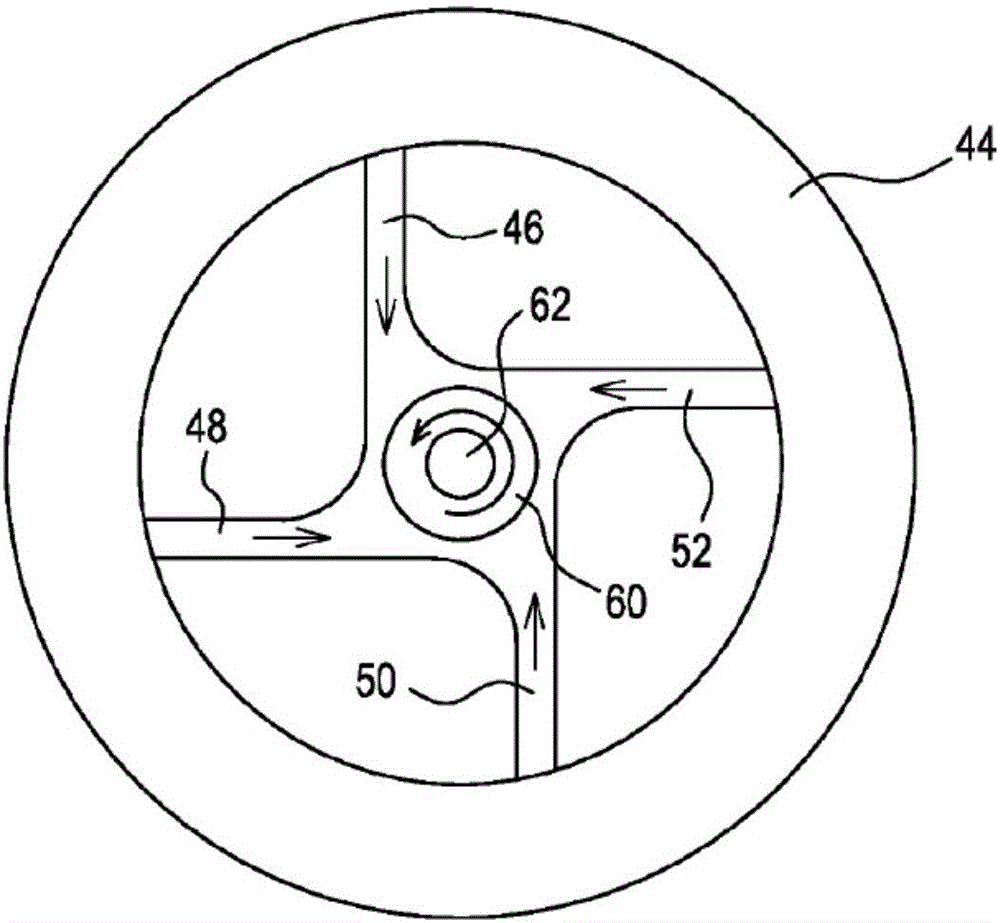
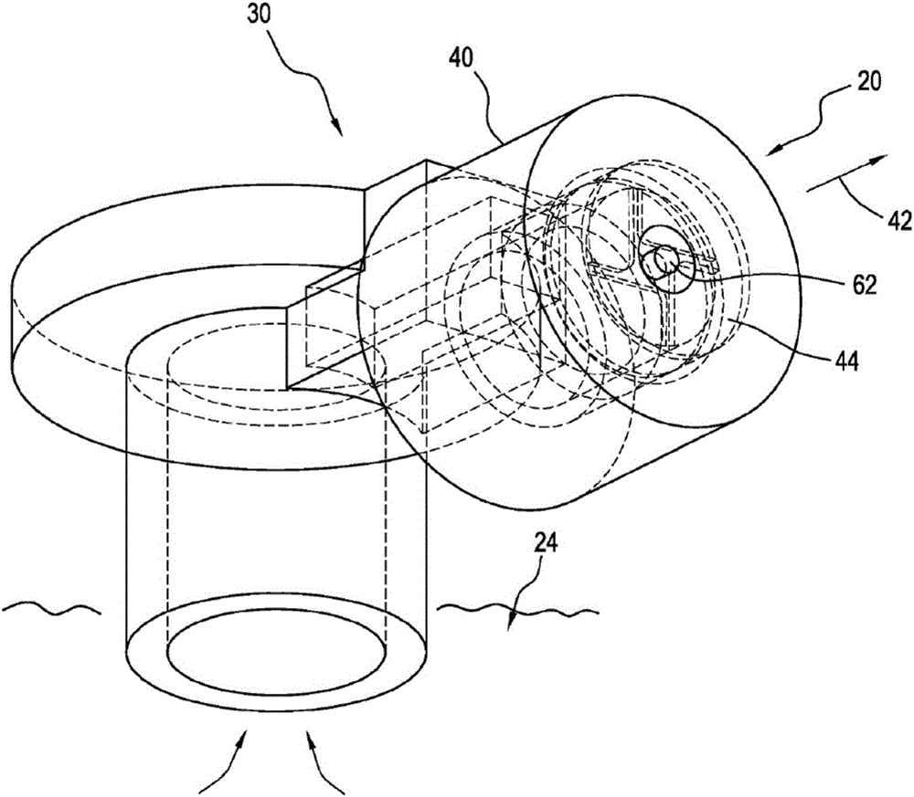
[0050] Figures 1A, 1B, 1C and 1D illustrate typical features of aerosol spray actuators and swirl cup nozzles used in the prior art, and these figures are described here to provide added background and context. Referring specifically to FIG. 1A, a typical transportable disposable propellant pressurized aerosol package 20 has a container 22 enclosing a liquid product 24 and an actuator 30 that controls a valve 32 mounted in a valve seat 34, A valve seat 34 is secured within a neck 36 of the container and is supported by a flange 38 of the container. Actuator 30 is depressed to open the valve and allow pressurized liquid to pass through nozzle 40 fitted with a spin cup to generate aerosol spray 42 . FIG. 1B shows the inner workings of a spin cup 44 used with a typical nozzle 40, where the four lumens 46, 48, 50 and 52 are aimed to produce four tangential flows indicated by the arrows in the lumens, which The tangential flow enters the spin chamber 60, where the continuously spu...


PUM


Abstract

A conformal, cup-shaped fluidic oscillator spray nozzle member (100, 200, 300, 400, 500) is configured to generate one or more oscillating sprays from fluid flowing into a substantially open proximal end and distally into a substantially closed distal end wall with one or more centrally located orifices defined therein. A multi-input, multi-output cup-shaped fluidic oscillator ( 200, 300, 400) is configured to generate a selected fluid spray from a plurality of (e.g., 2-8) fluid product inlets which are configured in interacting pairs and feed into a common interaction region of the fluidic nozzle geometry. Optionally, an outlet "A" can be positioned in the interaction region and allow for air entrainment into the interaction region or external oscillating spray streams to generate a foamed spray of fluid product.

Description

[0001] Related applications: [0002] This application claims the title "Multi-Inlet, Multi-Spray Fluidic Cup Nozzle with Common Interaction Area, Multi-Spray Fluidic Cup Nozzle and Jet Generation Method" filed on August 15, 2014 Shared Interaction Region and Spray Generation Method), the entire disclosure of which is incorporated herein by reference. This application is also related to the following commonly owned patent applications: [0003] (a) Filed April 19, 2011 and entitled "Method and Fluidic Cup apparatus for creating 2-D or 3-D spray patterns" U.S. Provisional Application No. 61 / 476,845; [0004] (b) PCT Application No. PCT / US12 / 34293, filed April 19, 2012, and entitled "Cup-shaped Fluidic Circuit, Nozzle Assembly and Method" (WlPO Publication WO 2012 / 145537)”; [0005] (c) U.S. Application No. 13 / 816,661, filed February 12, 2013, and entitled "Cup-shaped Fluidic Circuit, Nozzle Assembly and Method"; [0006] (d) U.S. Application No. 14 / 229,496, filed March 28, 2...

Claims


Application Information

Patent Timeline
Patent Type & Authority Applications(China)
IPC IPC(8): B05B1/34
CPCB05B1/14B05B1/08B05B1/3436
Inventor S·高普兰E·哈特兰夫特R·赫斯特
Owner DLHBOWLES INC
Learn More