Synchronous phase detection method for static frequency converter with direct voltage compensation

A static frequency converter, synchronous phase technology, applied in the phase angle between voltage and current, measurement of electrical variables, instruments, etc., can solve complex hardware loops, accurately detect the synchronization signal phase of static frequency converters, which is difficult and does not involve distortion Synchronization signal compensation and other problems, to achieve the effect of low implementation cost, small software calculation amount, and improved power factor

Active Publication Date: 2017-04-19
NR ELECTRIC CO LTD +1
View PDF5 Cites 2 Cited by
  • Summary
  • Abstract
  • Description
  • Claims
  • Application Information

AI Technical Summary

Problems solved by technology

Therefore, there are many difficulties in accurately detecting the phase of the synchronous signal of the static frequency converter
[0003] The patent "CN 201220367024.7" proposes a circuit that triggers the thyristor module after zero detection, but there is a complex hardware loop
[0004] The patent "CN 201310046799.3" proposes a new software phase-locked loop implementation method for SVC control system, but it does not involve the compensation of distorted synchronous signals, and the large-range frequency change conditions of static frequency converters

Method used


Image

  • Synchronous phase detection method for static frequency converter with direct voltage compensation
  • Synchronous phase detection method for static frequency converter with direct voltage compensation
  • Synchronous phase detection method for static frequency converter with direct voltage compensation

Examples


Embodiment 1

[0044] The static frequency converter synchronous phase detection method of this direct voltage compensation comprises the following steps:

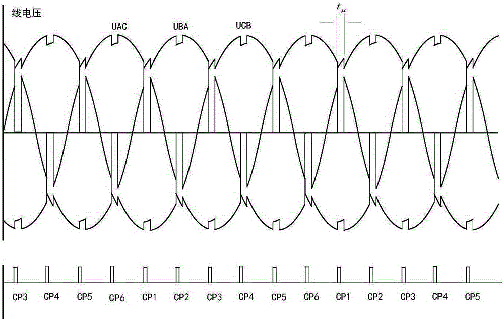
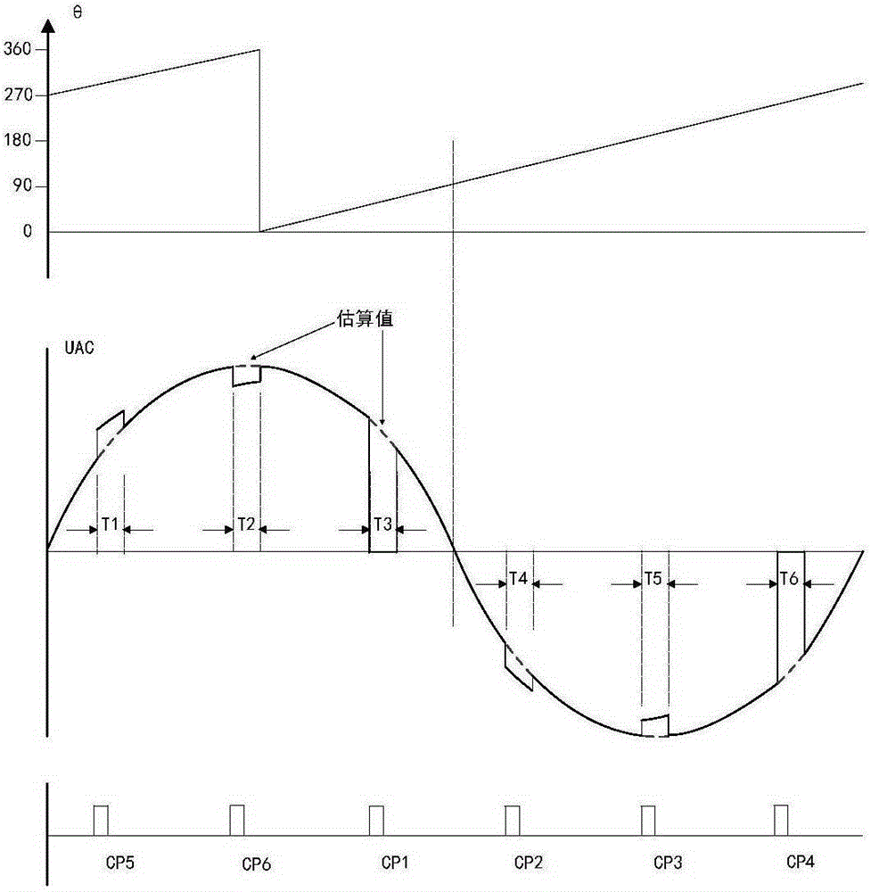
[0045] (1) Measure the three-phase line voltage on the AC side of the converter in real time, and eliminate the waveform distortion of the three-phase line voltage on the AC side in the commutation area by directly estimating and compensating the waveform of the actual frequency conversion line voltage to obtain a sinusoidal estimate;

[0046] (2) Then use the software phase-locked loop to carry out real-time phase-locking on the estimated quantity, and realize the robust synchronous phase detection of the static frequency converter.

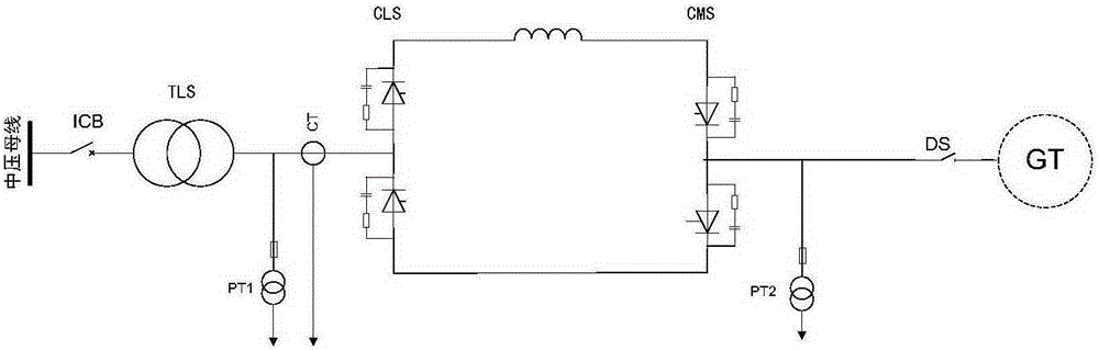
[0047] Such as figure 1 As shown, a group of PTs is installed on the AC side of the machine-side converter CMS to measure the three distorted lines

[0048] Voltage U AC , U BA and U CB .

[0049] On the rising edge of the trigger pulse CP1~CP6, according to the number of the current trigger pulse, th...


PUM


Abstract

The invention discloses a synchronous phase detection method for a static frequency converter with direct voltage compensation. The method comprise: (1) measuring the AC-side three-phase line voltage of the converter in real time, and eliminating the waveform distortion of the AC-side three-phase line voltage in a commutation area by directly pre-estimating and compensating the waveform of actual frequency conversion line voltage so as to obtain a sine estimated amount; (2) using a software phase-locked loop to perform real-time phase locking on the estimated amount to achieve robust synchronous phase detection of the static frequency converter. The method uses only a single PT to realize the accurate tracking of the synchronous phase of the static frequency converter under the variable frequency conditions, so as to ensure that the a converter bridge does not generate commutation failure, to ensure the safe equipment operation, and to improve the power factor on the output side of the static frequency converter. The algorithm does not depend on a complex hardware filter circuit, and is small in software calculation amount, and is low in cost.

Description

technical field [0001] The invention relates to a phase detection method of a frequency conversion synchronous signal of a static frequency converter, in particular to a phase detection method of a static frequency converter with direct voltage compensation. Background technique [0002] Such as figure 1 As shown, in order to ensure that the commutation failure of the machine-side converter bridge does not occur and improve the power factor of the output side of the static frequency converter, it is necessary to accurately track the phase of the synchronization signal of the machine-side converter. However, due to the commutation of the thyristors, the measured synchronous signal of the stationary frequency converter is severely distorted, as figure 2 shown. Secondly, when the rotation speed of the generator is different, the fundamental frequency of the synchronous signal of the generator-side converter also varies in a large range. Therefore, there are many difficultie...

Claims


Application Information

Patent Timeline
Patent Type & Authority Applications(China)
IPC IPC(8): G01R25/00
Inventor 刘腾刘为群石祥建吴龙任百群
Owner NR ELECTRIC CO LTD
Why Eureka
Try Eureka