
Floating machine

A floating machine and floating wheel technology, applied in the field of floating machines, can solve problems such as lack of stability, difficulty in popularization, and low effectiveness

Inactive Publication Date: 2017-03-29
洪为帮
View PDF8 Cites 0 Cited by
  • Summary
  • Abstract
  • Description
  • Claims
  • Application Information

AI Technical Summary

Problems solved by technology

[0002] At present, clean energy sources such as wind energy, solar energy, and tidal energy have been well developed, but these clean energy sources without emissions lack stability because they are easily affected by the weather; although some people have also developed relatively stable buoyancy energy, However, most of them are limited to relying on rivers, lakes and seas, which are restricted by geographical conditions and are difficult to popularize; although some develop buoyancy energy without rivers, lakes and seas, their facilities or devices are too large and heavy, and the investment is high. The practicability is not strong; some use additional kinetic energy to cooperate, the net output kinetic energy is limited, and the actual effect is not high

Method used

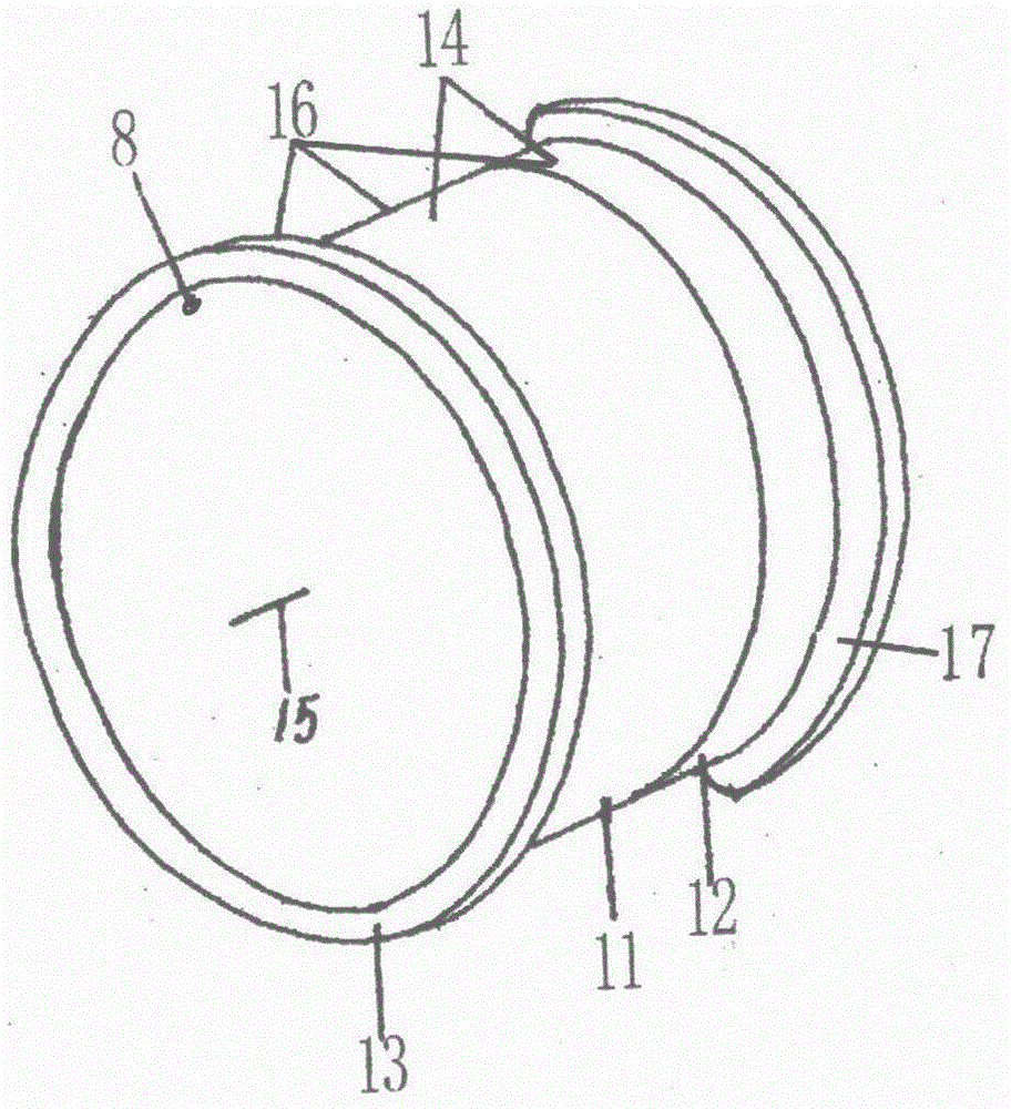
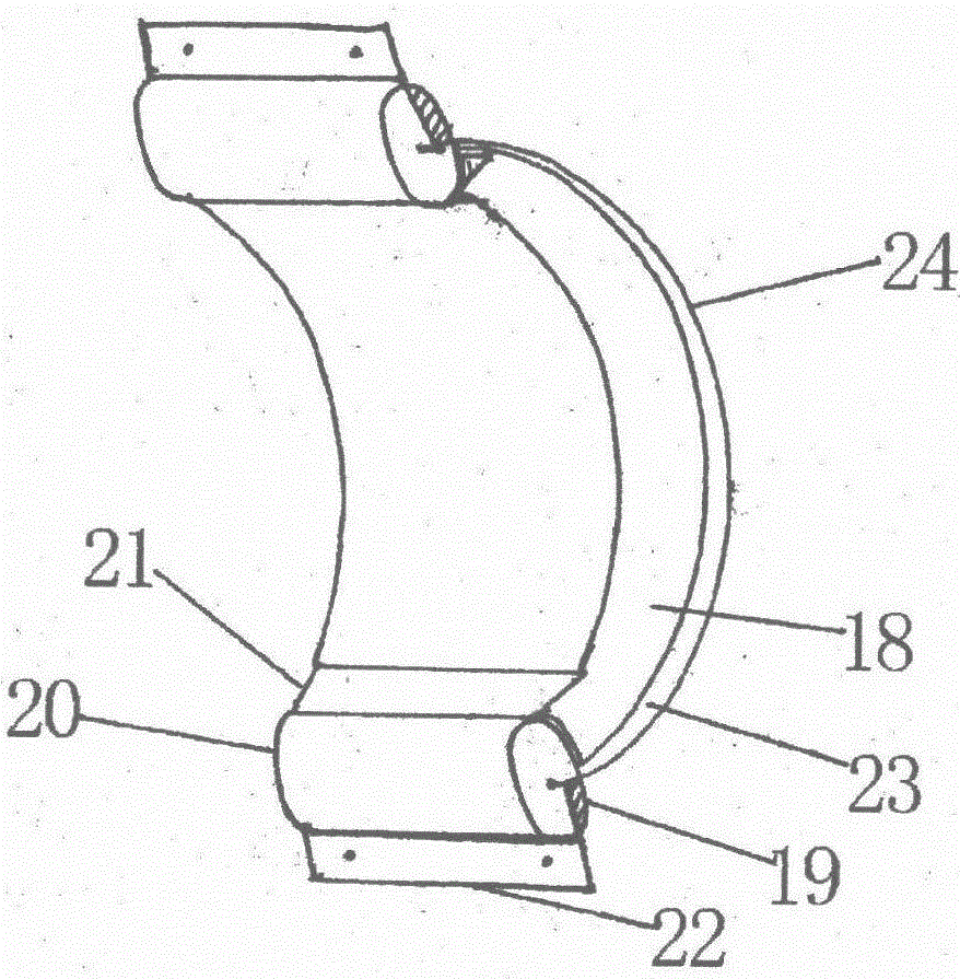

Image

  • Floating machine
  • Floating machine
  • Floating machine

Examples


Embodiment Construction

[0019] Such as Figure 5 A floating machine is shown in .

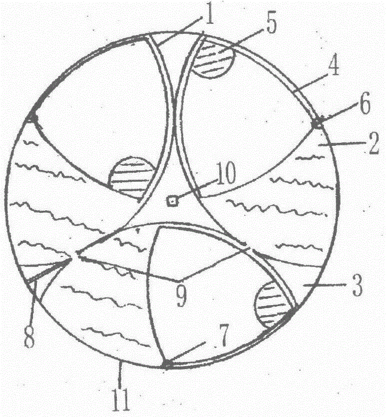
[0020] The cross section of the gravity disk device of the present invention is viewed as figure 1 As shown in , use three arc-shaped partitions 1 to divide the inner chamber of the gravity plate 11 into three inner water tanks 2, and seal the three equally divided air chambers 3 at the same time, making three single bodies is equivalent to half the volume of the inner water tank 2 The inner buoyancy tank 4 of the inner buoyancy tank 4 is installed in each inner water tank 2 respectively, the rotating shaft 5 is fixed on the sharp corner of the inner buoyancy tank 4, and the weight 6 is fixed on the right corner of the inner buoyancy tank 4. At the gap, the weight of the weight 6 is the maximum value of the buoyancy of the inner buoyancy tank 4, the shaft buckle 7 is fastened to the rotating shaft 5 and fixed at the midpoint of the outer edge of the inner water tank 2, and the water injection channel 8 passes through...


PUM


Abstract

The invention provides a floating machine. A kinetic energy forming device of the floating machine comprises a progressive floating device and a sealing water device matched with the progressive floating device. The progressive floating device and the sealing water device are arranged on the two sides of a primary floating device correspondingly to sublate positive and negative energy of each side of the primary floating device, so that buoyancy energy on one side of the primary floating device can be sustainably and automatically generated, gravitational energy of the other side of the primary floating device can be progressively accumulated, and the buoyancy energy and the gravitational energy can be combined so as to be output. According to the floating machine, the primary floating device comprises a device capable of switching and enlarging the buoyancy energy into gravitational energy, so that working efficiency is further improved. The floating machine use gas but does not burn gas, use water but does not consume water, and used water is little; and the floating machine is economical, environmentally friendly, portable and efficient.

Description

technical field [0001] The invention relates to a non-emission engine, which is a floating machine. Background technique [0002] At present, clean energy sources such as wind energy, solar energy, and tidal energy have been well developed, but these clean energy sources without emissions lack stability because they are easily affected by the weather; although some people have also developed relatively stable buoyancy energy, However, most of them are limited to relying on rivers, lakes and seas, which are restricted by geographical conditions and are difficult to popularize; although some develop buoyancy energy without rivers, lakes and seas, their facilities or devices are too large and heavy, and the investment is high. The practicability is not strong; some also use extra kinetic energy to cooperate, the net output kinetic energy is limited, and the actual effect is not high. Contents of the invention [0003] The problem to be solved by the present invention is to o...

Claims


Application Information

Patent Timeline
IPC IPC(8): F03B17/04
CPCF03B17/04
Inventor 洪维邦
Owner 洪为帮
Learn More