
Tooth shape grinding device for connecting rods

A grinding device and tooth type technology, which is applied in the direction of grinding devices, grinding drive devices, grinding machine tools, etc., can solve the problems of large grinding workload, high labor load intensity, and high grip point, so as to shorten the repair cycle and reduce manpower Consumption, the effect of improving product quality

Pending Publication Date: 2017-03-29
CRRC LUOYANG CO LTD
View PDF6 Cites 0 Cited by
  • Summary
  • Abstract
  • Description
  • Claims
  • Application Information

AI Technical Summary

Problems solved by technology

[0003] The connecting rods of the known DF8B and G models are composed of the connecting rod cover 8 and the connecting rod body 7 through tooth meshing connection. When the teeth are worn and repaired by welding, the repaired tooth profile needs to be ground. The grinding workload is large and the efficiency is high. low, labor time, long
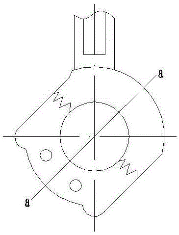
At present, in order to improve the quality of connecting rod repair products, the workshop adopts the method of boring to repair the connecting rod. In order to leave a machining allowance for the boring, the dimension of the connecting rod a direction can only be controlled by manual grinding, such as figure 1 As shown, this puts a lot of pressure on the work of repairing the connecting rod
Manual mechanical grinding, high grip point, large swing during push and pull, heavy labor load, easy fatigue, frequent changes in posture, resulting in a large difference in the dimension of the connecting rod in the a direction, resulting in out-of-roundness, resulting in product scrapping or extensive rework

Method used


Image

  • Tooth shape grinding device for connecting rods
  • Tooth shape grinding device for connecting rods
  • Tooth shape grinding device for connecting rods

Examples


Embodiment Construction

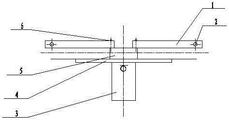
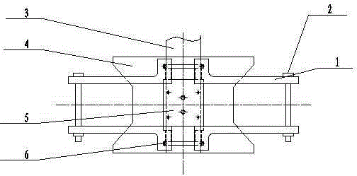
[0014] Such as figure 2 , 3 As shown, the present invention comprises a fastening plate 1, an I-shaped plate 4, and a cylinder 5; the cylinder 5 is fixed on the connecting rod between the upper and lower sides of the I-shaped plate 4 with bolts, and the four fastening plates 1 are respectively passed through the bolts 6 Fixed on the piston of the cylinder 5, the four fastening plates 1 are L-shaped respectively, and the bottom edges of every two L-shaped fastening plates 1 are fixed by bolts 6, and the four L-shaped fastening plates 1 form a frame Clamp the piston of the cylinder 5, and fix the fastening plate 1 on the piston of the cylinder 5 through the bolt 6. When the cylinder 5 is working, the reciprocating motion of the cylinder piston can drive the four fastening plates 1 along the I-shaped plate 4 The connecting rod between the upper and lower sides, that is, image 3 Reciprocating linear motion in the up and down direction of the center, screw holes are provided on...


PUM


Abstract

The invention provides a tooth shape grinding device for connecting rods and particularly provides a tooth shape grinding device suitable for welding repaired connecting rods of DF8B and G locomotives. The tooth shape grinding device mainly solves the problem of product scrapping or reworking caused by connecting rod out-of-circularity due to the high grip point, push-pull process large swinging, high labor intensity and frequent posture change of manual mechanical grinding. A cylinder of the grinding device is fixed to a connecting rod between the upper and lower edges of an I-shaped plate by bolts, and four fastening plates are separately fixed to a piston of the cylinder by bolts. In use, the I-shaped plate is mounted in holes in the large end of the connecting rod, the piston of the cylinder is fixed to a connecting rod cover, and the connecting rod cover is driven to move together and ground by utilizing the linear reciprocating movement of the cylinder. The tool is small in size, light in weight, convenient to mount, even in stress, low in acting point, adjustable in speed, stable in movement, small in swinging and small in noise. The quality of the connecting rod ground by the device is great, and the efficiency is high.

Description

technical field [0001] The invention relates to a tooth profile grinding tool for connecting rods, in particular to a tooth profile grinding device suitable for welding and repairing connecting rods of two types of vehicles, DF8B and G. [0002] technical background [0003] The connecting rods of the known DF8B and G models are composed of the connecting rod cover 8 and the connecting rod body 7 through tooth meshing connection. When the teeth are worn and repaired by welding, the repaired tooth profile needs to be ground. The grinding workload is large and the efficiency is high. Low, labor time, long. At present, in order to improve the quality of connecting rod repair products, the workshop adopts the method of boring to repair the connecting rod. In order to leave a machining allowance for the boring, the dimension of the connecting rod a direction can only be controlled by manual grinding, such as figure 1 As shown, a lot of pressure is added to the work of repairing t...

Claims


Application Information

Patent Timeline
IPC IPC(8): B24B37/27B24B37/34B24B47/10
CPCB24B37/27B24B37/34B24B47/10
Inventor 杨艳曾德平熊倩倩
Owner CRRC LUOYANG CO LTD
Learn More