Hypersonic flight vehicle cooling and semiconductor thermoelectric power generation integrated system

A technology of thermoelectric power generation and hypersonic speed, applied in the direction of generators/motors, electrical components, etc., can solve problems such as insufficient fuel heat sinks, achieve the effects of reducing fuel consumption and maximum temperature, high reliability, and reducing quality penalties

Inactive Publication Date: 2017-03-22
HARBIN INST OF TECH
View PDF4 Cites 0 Cited by
  • Summary
  • Abstract
  • Description
  • Claims
  • Application Information

AI Technical Summary

Problems solved by technology

[0006] The purpose of the present invention is to meet the thermal protection and power supply requirements of long-endurance hypersonic flight, provide an integrated system for hypersonic aircraft cooling and semiconductor thermoe...

Method used


Image

  • Hypersonic flight vehicle cooling and semiconductor thermoelectric power generation integrated system
  • Hypersonic flight vehicle cooling and semiconductor thermoelectric power generation integrated system

Examples


Embodiment approach 1

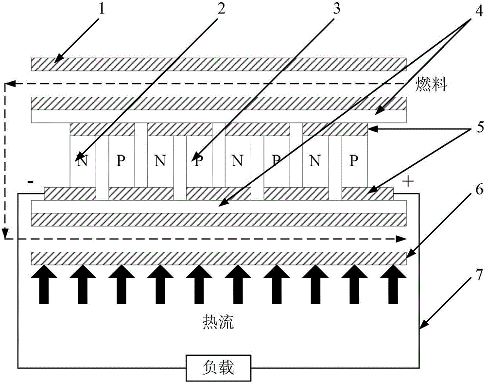
[0023] Implementation mode one: the following combination figure 1 The present embodiment will be described in detail. The hypersonic aircraft cooling and semiconductor thermoelectric power generation integrated system described in this embodiment includes a low-temperature channel 1, a semiconductor thermoelectric power generation device, multiple heat-conducting insulating layers 4 and a high-temperature channel 6;

[0024] The semiconductor thermoelectric power generation device block includes a plurality of N-type semiconductor thermoelectric materials 2, a plurality of P-type semiconductor thermoelectric materials 3 and a plurality of guide fins 5, the N-type semiconductor thermoelectric materials 2 and the P-type semiconductor thermoelectric materials 3 are arranged at intervals, And through the deflector 5 in series;

[0025] Both sides of the semiconductor thermoelectric power generation device are provided with a thermally conductive insulating layer 4 closely attach...

Embodiment approach 2

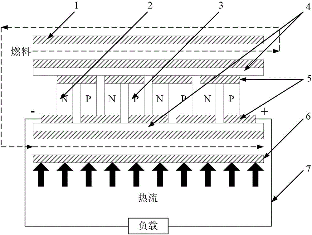
[0028] Implementation mode two: the following combination figure 2 The present embodiment will be described in detail. This embodiment is a further limitation of the hypersonic aircraft cooling and semiconductor thermoelectric power generation integrated system described in Embodiment 1. In this embodiment, the entrance of the low-temperature passage 1 and the entrance of the high-temperature passage 6 are located at the semiconductor thermoelectric power generation device. same side.

[0029] The opposite flow direction of the fuel in the low-temperature channel 1 and the high-temperature channel 6 causes uneven temperature difference, which is not conducive to improving the thermoelectric conversion efficiency, so the system structure is further improved, such as figure 2 shown. Both the inlet of the low-temperature channel 1 and the inlet of the high-temperature channel 6 are located on the left side of the semiconductor thermoelectric power generation device,

[0030]...


PUM


Abstract

The invention discloses a hypersonic flight vehicle cooling and semiconductor thermoelectric power generation integrated system, and relates to the hypersonic flight vehicle cooling and semiconductor thermoelectric power generation integration technology. The aim is to satisfy the thermal protection and power supply demands of the long-endurance hypersonic flight. N-type semiconductor thermoelectric materials (2) and P-type semiconductor thermoelectric materials (3) of the system are arranged at intervals and are orderly connected in series to form a semiconductor thermoelectric power generation device through a flow deflector (5); heat-conducting insulating layers (4) tightly clung to the flow deflector (5) are arranged at two sides of the semiconductor thermoelectric power generation device; the outsides of two heat-conducting insulating layers (4) are respectively a low-temperature channel (1) and a high-temperature channel (6), and the low-temperature channel (1) is communicated with the high-temperature channel (6). A cooling system and a power generation system are integrated through the system, the structure quality is lowered, the quality punishment is reduced, and the system is suitable for a hypersonic flight vehicle.

Description

technical field [0001] The invention relates to the integrated technology of hypersonic aircraft cooling and semiconductor thermoelectric power generation. Background technique [0002] The long-term flight of a hypersonic vehicle at a high flight Mach number will greatly increase the heat flux density at the leading edge of the airframe and the combustion chamber, making thermal protection one of the key technologies for hypersonic flight. At the same time, for long-endurance hypersonic vehicles, a single battery can no longer meet the power supply demand, and a power supply system that can continuously generate electricity must be introduced. [0003] The extremely high total incoming flow and possible supersonic combustion lead to very high thermal loads on the hypersonic vehicle leading edge and engine combustion chamber. For the active cooling thermal protection scheme necessary for long endurance, the limited allowable temperature of the metal wall material results in...

Claims


Application Information

Patent Timeline
IPC IPC(8): H02N11/00
CPCH02N11/002
Inventor 秦江程昆林章思龙鲍文
Owner HARBIN INST OF TECH
Why Eureka
Try Eureka