
Intelligent submersible motor with built-in controller

A submersible motor and controller technology, applied in the direction of connection with control/drive circuit, electrical components, electromechanical devices, etc., can solve problems such as increased heat generation, affecting the service life of the controller, and mechanical oil seals cannot be effectively lubricated

Pending Publication Date: 2017-03-22
台州市百施度工贸有限公司
View PDF0 Cites 3 Cited by
  • Summary
  • Abstract
  • Description
  • Claims
  • Application Information

AI Technical Summary

Problems solved by technology

Most of the submersible motors on the existing deep well pumps have their motor shafts fixed on the end cover, which will cause micro-vibrations of the end cover during operation. These vibrations will easily cause the motor shaft to shift, causing its concentricity to change. As a result, the phenomenon of rotor sweeping occurs, which will double the current inside the motor, increase the internal heat generation, and easily cause damage to components; and since the mechanical oil seal and the bearing are located in the same groove, in order to accommodate the mechanical oil seal And bearings, the depth of the groove on the end cover is usually made relatively deep, so that when the heat transfer oil in the motor cavity is not filled or reduced, the internal mechanical oil seal may not be lubricated effectively, resulting in dry wear of the mechanical seal; and That is, the built-in controller of the existing submersible motor will generate a certain amount of heat and bear the pressure of the external water and the corrosion of the heat transfer oil when it is working. Factors such as poor heat dissipation, deep water pressure, and corrosion of the heat transfer oil will affect the normal operation of the controller and service life

Method used


Image

  • Intelligent submersible motor with built-in controller
  • Intelligent submersible motor with built-in controller

Examples


Embodiment Construction

[0015] The following descriptions are only preferred embodiments of the present invention, and do not limit the protection scope of the present invention. The present invention will be further described below in conjunction with the accompanying drawings and embodiments.

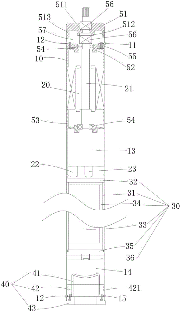
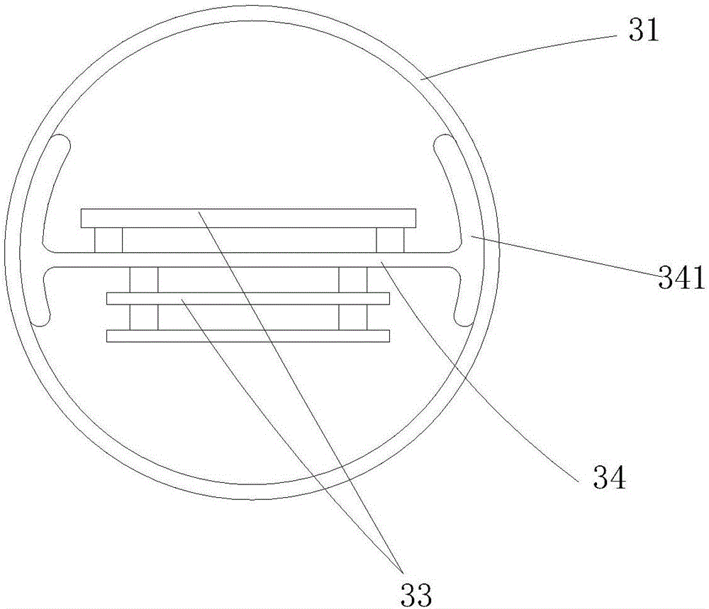
[0016] Examples, see figure 1 and figure 2 As shown: an intelligent submersible motor with a built-in controller, including a body 10, the body 10 is hollow inside and has a through structure at both ends. A brushless DC stator / rotor assembly 20, a variable frequency sealing device 30, a base sealing assembly 40 and an end cover sealing assembly are arranged inside the machine body 10. The end cover sealing assembly includes a motor end cover 51, an upper bearing seat 52, a lower bearing seat 53, The bearing 54, the top clamping plate 55 and the mechanical oil seal 56, the end of the motor end cover 51 is fixedly connected with the end of the body 10, and an outer mechanical oil seal groove 511 and an inne...


PUM


Abstract

The invention discloses an intelligent submersible motor with a built-in controller. A brushless direct current fixed / rotor assembly, a frequency conversion sealing device, a base sealing assembly and an end cap sealing assembly are arranged in the motor body. The frequency conversion sealing device matches the brushless direct current fixed / rotor assembly and the base sealing assembly. The end cap sealing assembly is provided with a shaft hole used for positioning a rotation shaft, and comprises a motor end cap, an upper bearing seat, a lower bearing seat, bearings, a pressing plate and mechanical oil seals. The motor end cap is provided with upper and inside mechanical oil seal grooves. The mechanical oil seals are located in upper and inside mechanical oil seal grooves. The pressing plate abuts against a tension bead ring. Upper and lower bearing seats abut against the end part of the brushless direct current fixed / rotor assembly. The bearings are located in the upper bearing and the lower bearing seat, and are used in conjunction with the rotation shaft. The intelligent submersible motor provided by the invention has the advantages that the sealing effect is good; the concentricity of the rotation shaft of the motor can be effectively guaranteed; heat can be effectively eliminated; and internal and external pressure of the motor can be balanced.

Description

technical field [0001] The invention belongs to the technical field of deep well pumps, in particular to an intelligent submersible motor with a built-in controller. Background technique [0002] At present, the deep well pump is a water-lifting machine that is directly connected to the motor and the water pump and submerges into the water. It is suitable for extracting groundwater from deep wells, and can also be used for water-lifting projects such as rivers, reservoirs, and canals. Deep well pumps are immersed in groundwater wells for pumping and transporting water. A kind of pump is widely used in farmland drainage and irrigation, industrial and mining enterprises, urban drainage and sewage treatment, etc. Most of the submersible motors on the existing deep well pumps have their motor shafts fixed on the end cover, which will cause micro-vibrations of the end cover during operation. These vibrations will easily cause the motor shaft to shift, causing its concentricity to...

Claims


Application Information

Patent Timeline
IPC IPC(8): H02K5/132H02K5/128H02K11/30
CPCH02K5/1285H02K5/132
Inventor 施法定
Owner 台州市百施度工贸有限公司
Learn More