
Instantaneous overcurrent protection circuit of medium-high voltage variable-frequency speed regulating device and frequency converter

A technology of overcurrent protection circuit and speed regulating device, which is applied in the direction of overcurrent protection, measuring devices, instruments, etc., can solve the problems of narrow working frequency band, low linearity, hysteresis, etc., to improve input impedance and reduce Output impedance, the effect of avoiding production accidents

Inactive Publication Date: 2017-03-22
DAYU ELECTRIC
View PDF8 Cites 5 Cited by
  • Summary
  • Abstract
  • Description
  • Claims
  • Application Information

AI Technical Summary

Problems solved by technology

Although the direct series sampling resistor method is simple, reliable, undistorted, and fast, it has loss and is not isolated. It is only suitable for small currents that do not require isolation. It is mostly used in small-capacity low-voltage frequency conversion speed control devices.
The current transformer method has low loss, is isolated from the main circuit, and is convenient and flexible to use; but it also has low linearity, narrow operating frequency band, and a certain hysteresis, and is mostly used in medium, high-voltage, and high-current occasions

Method used


Image

  • Instantaneous overcurrent protection circuit of medium-high voltage variable-frequency speed regulating device and frequency converter
  • Instantaneous overcurrent protection circuit of medium-high voltage variable-frequency speed regulating device and frequency converter
  • Instantaneous overcurrent protection circuit of medium-high voltage variable-frequency speed regulating device and frequency converter

Examples


Embodiment Construction

[0033]The present invention will be described in further detail below in conjunction with the accompanying drawings and embodiments.

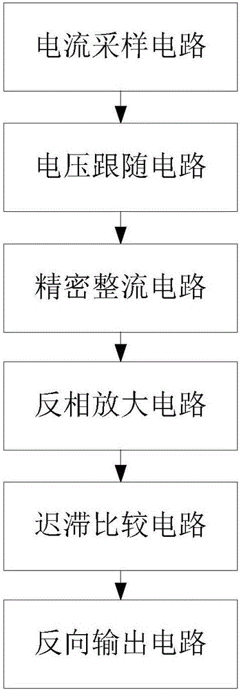
[0034] see figure 1 As shown, the embodiment of the present invention provides an instantaneous overcurrent protection circuit for a medium and high voltage frequency conversion speed regulating device, including:

[0035] The current sampling circuit, the input terminal of the current sampling circuit is connected with the A phase and the C phase of the output terminal of the frequency conversion speed control device, and is used to convert the current signals of the A phase and the C phase output by the frequency conversion speed control device into the A phase and the C phase voltage signal;

[0036] A voltage follower circuit, the input end of the voltage follower circuit is connected to the output end of the current sampling circuit, the voltage follower circuit respectively receives the voltage signals of the A phase and the C phase, and...


PUM


Abstract

The invention discloses an instantaneous overcurrent protection circuit of a medium-high voltage variable-frequency speed regulating device and a frequency converter. The circuit comprises a current sampling circuit, a voltage following circuit, a precision rectifier circuit, an inverting amplifier circuit, a hysteresis comparison circuit and a reverse output circuit, wherein an input end of the current sampling circuit is connected with an A phase and a C phase of an output end of the variable-frequency speed regulating device; the input end of the voltage following circuit is connected with the output end of the current sampling circuit; the input end of the precision filter circuit is connected with the output end of the voltage following circuit; the input end of the inverting amplifier circuit is connected with the output end of the precision rectifier circuit; the input end of the hysteresis comparison circuit is connected with the output end of the inverting amplifier circuit; and the input end of the reverse output circuit is connected with the output end of the hysteresis comparison circuit. The frequency converter comprises a master control chip and an overcurrent protection circuit; the master control chip stops power output of the medium-high voltage variable-frequency speed regulating device according to the an overcurrent protection signal output by the overcurrent protection circuit and cuts off high voltage input.

Description

technical field [0001] The invention relates to the technical field of frequency conversion speed regulation, in particular to an instantaneous overcurrent protection circuit and a frequency converter of a medium and high voltage frequency conversion speed regulation device. Background technique [0002] During the operation of medium and high voltage frequency conversion speed control devices, overcurrent faults often occur due to abnormal input voltage, sudden or abnormal loads, and low power of frequency conversion speed control devices. When the medium and high voltage frequency conversion speed control device has an overcurrent fault, if it cannot be found and dealt with immediately, the medium and high voltage frequency conversion speed control device and external equipment will be damaged, and production accidents will occur. In order to protect medium and high voltage frequency conversion speed control devices and external equipment and avoid production accidents, th...

Claims


Application Information

Patent Timeline
IPC IPC(8): H02H3/08G01R19/00
CPCH02H3/08G01R19/0092
Inventor 李鹏李崇波宁国云王怡华
Owner DAYU ELECTRIC
Learn More