Tape winding device
A winding device and adhesive tape technology, which is applied in the direction of insulation/armored cable repair equipment, etc., can solve the problems of insulating tapes being difficult to stick and waste, and achieve the effects of improving winding efficiency, preventing mutual sticking, and improving convenience
- Summary
- Abstract
- Description
- Claims
- Application Information
AI Technical Summary
Problems solved by technology
Method used
Image


Examples
Embodiment 1
[0033] Such as figure 1 As shown, the present invention includes a housing 1, the housing 1 is a columnar structure, the housing 1 is provided with an opening 2 along its axial direction, and the side of the housing 1 close to the opening 2 is provided with an arc-shaped groove 3, and the arc-shaped concave The two ends of groove 3 are provided with catch 16, and catch 16 can be made of rubber material or nylon material, and one end of catch 16 is connected with the housing on the lower side of arc-shaped groove 3 through rotating shaft 19, and the other end of catch 16 is integrated. Forming the hook 17, the hanging point 18 that is integrally formed on the housing on the upper side of the arc groove 3 and the hook 17;
[0034] The size of the opening 2 is consistent with the outer diameter of the arc-shaped groove 3, and the arc-shaped groove 3 is provided with an elongated hole 4 parallel to the central axis of the housing 1, and an accommodating cavity 5 is integrally form...
Embodiment 2
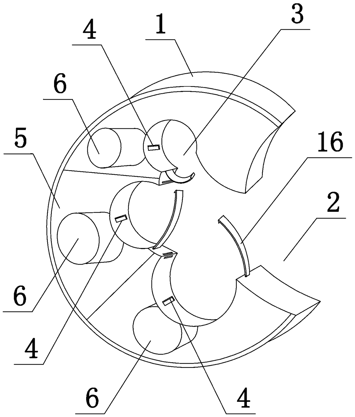
[0037] Such as figure 2As shown, the present invention includes a housing 1, the housing 1 is a columnar structure, the housing 1 is provided with an opening 2 along the central axis direction, and the side of the housing 1 close to the opening 2 is provided with three arc-shaped grooves 3, the arc-shaped Groove 3 two ends are provided with catch 16, and one end of catch 16 is connected with the housing of the lower side of arc groove 3 by rotating shaft 19, and the other end of catch 16 integrally forms hook 17, and the arc groove 3 The hanging point 18 matched with the hook 17 is integrally formed on the upper shell;
[0038] The outer diameters of the three arc-shaped grooves 3 are different in size, and each arc-shaped groove 3 is provided with an elongated hole 4 parallel to the central axis of the housing 1, and a housing cavity 5 is integrally formed in the housing 1 to accommodate Three positioning columns 6 parallel to the central axis of the housing 1 are integrall...
Embodiment 3
[0041] Such as image 3 As shown, the present invention includes a housing 1, the housing 1 is a columnar structure, the housing 1 is provided with an opening 2 along the central axis direction, and the side of the housing 1 close to the opening 2 is provided with three arc-shaped grooves 3, the arc-shaped Groove 3 two ends are provided with catch 16, and one end of catch 16 is connected with the housing of the lower side of arc groove 3 by rotating shaft 19, and the other end of catch 16 integrally forms hook 17, and the arc groove 3 The hanging point 18 matched with the hook 17 is integrally formed on the upper shell;
[0042] Each arc-shaped groove 3 is provided with an elongated hole 4 parallel to the central axis of the housing 1, and three accommodation cavities 5 are integrally formed in the housing 1, and each accommodation cavity 5 is integrally formed with the housing 1. The axis is parallel to the positioning column 6.
[0043] The structure of this embodiment is ...
PUM
 Abstract
Description
Claims
Application Information
 - R&D
- Intellectual Property
- Life Sciences
- Materials
- Tech Scout
- Unparalleled Data Quality
- Higher Quality Content
- 60% Fewer Hallucinations
Browse by: Latest US Patents, China's latest patents, Technical Efficacy Thesaurus, Application Domain, Technology Topic, Popular Technical Reports.
© 2025 PatSnap. All rights reserved.Legal|Privacy policy|Modern Slavery Act Transparency Statement|Sitemap|About US| Contact US: help@patsnap.com