Explosion-proof safety top cover for battery

A top cover and safety technology, which is applied in the direction of battery cover/end cover, battery pack parts, battery box/coating, etc., can solve the problem of reduced strength of pressure relief valve, high battery scrap rate, affecting battery capacity, cycle and shelf performance To achieve the effect of preventing explosion safety accidents, improving explosion-proof safety performance, and good industrial application prospects

Active Publication Date: 2017-03-22
HEFEI GUOXUAN HIGH TECH POWER ENERGY
View PDF4 Cites 2 Cited by
  • Summary
  • Abstract
  • Description
  • Claims
  • Application Information

AI Technical Summary

Problems solved by technology

At present, there are usually two solutions: one is to reduce the opening threshold of the pressure relief valve, that is, to reduce the pressure limit of the pressure relief valve, so that the pressure relief valve is easier to rupture, but this will cause the strength of the pressure relief valve to decrease. It is easy to be damaged during use, and the low opening threshold makes the pressure relief valve rupture under normal conditions, such as during the formation process, resulting in a high scrap rate of the battery; another way is to add easy-to-produc Gas substances, such as adding anti-overcharge additives that can decompose and generate gas in the electrolyte, will increase the internal gas production and advance the gas production reaction time when the battery is damaged by overcharging, acupuncture, etc., making the pressure relief The valve is opened quickly in advance, but these gas-producing substances will obviously affect the capacity, cycle and shelf performance of the battery, so there are certain problems in industrialization

Method used


Image

  • Explosion-proof safety top cover for battery
  • Explosion-proof safety top cover for battery
  • Explosion-proof safety top cover for battery

Examples


Embodiment Construction

[0018] The present invention will be further described below in conjunction with accompanying drawing:

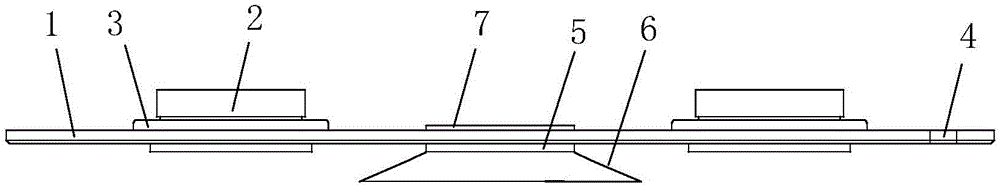
[0019] Such as figure 1 The explosion-proof safety top cover of the battery shown includes a top cover substrate 1, on which a pole 2, a metal spacer 3 and a liquid injection hole 4 are arranged, and the metal spacer 3 and the pole 2 are riveted or welded. The electrical connection is realized in a manner, and one or two of the poles 2 are insulated from the metal spacer 3 through insulating gaskets. The top cover substrate 1 is also provided with an explosion-proof assembly, and the explosion-proof assembly includes a gas collection hood base 5 fixed with the top cover substrate 1, a gas collection hood 6 connected to the gas collection hood base 5, and a gas collection hood 6 placed in the center of the gas collection hood base 5. Pressure relief valve 7 at.

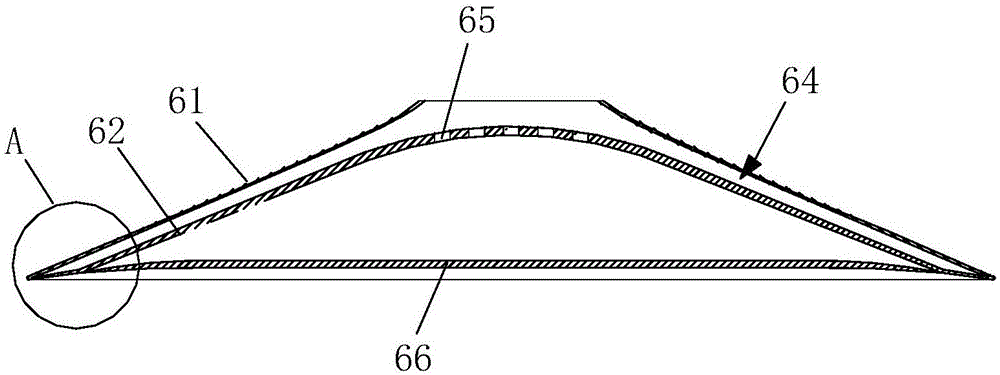
[0020] Further, such as figure 2 , image 3 , Figure 4 As shown, the gas collecting hood 6 has a gradually...


PUM


Abstract

The invention relates to an explosion-proof safety top cover for a battery. The explosion-proof safety top cover comprises a top cover substrate, wherein polar columns, metal cushion blocks and a liquid injecting hole are arranged on the top cover substrate; an explosion-proof assembly is also arranged on the top cover substrate; and the explosion-proof assembly comprises a gas collecting cover base fixed on the top cover substrate, a gas collecting cover connected with the gas collecting cover base, and a pressure release valve arranged in the center in the gas collecting cover base. By virtue of the technical scheme, the explosion-proof assembly can perform quick reaction to start the pressure release valve when the battery suffers from a severe gas reaction caused by overcharging, short circuit and the like, to release internal pressure of the battery in time so as to prevent from an explosion safety accident; meanwhile, the interior of the explosion-proof assembly has an electrolyte separating function, so that corrosion to an external flow-guiding electrode plate of the battery and possibly-caused personal injury by an electrolyte ejected from the interior of the battery at high temperature and high pressure can be avoided; and in addition, the explosion-proof safety performance of the battery can be improved without affecting the production yield and battery performance, so that the explosion-proof safety top cover has relatively high industrial application prospect.

Description

technical field [0001] The invention relates to the field of batteries, in particular to an explosion-proof safety top cover for batteries. Background technique [0002] The power battery will undergo a violent gas production reaction under the conditions of acupuncture, overcharging, short circuit, etc., causing the internal pressure of the battery to increase rapidly, and it is likely to explode and cause a safety accident. For this reason, a pressure relief valve is installed on the top cover of the current power battery. The pressure relief valve has a certain pressure limit. When the internal pressure of the battery reaches the pressure limit of the pressure relief valve, the pressure relief valve will rupture, thereby releasing the battery Internal air pressure to prevent safety accidents. But for the square aluminum case battery, when the inside of the battery violently produces gas, because the aluminum case is relatively soft, and the case in the width direction ...

Claims


Application Information

Patent Timeline
Patent Type & Authority Applications(China)
IPC IPC(8): H01M2/04H01M2/02H01M2/12H01M50/10H01M50/147H01M50/30
CPCH01M50/10H01M50/147H01M50/30Y02E60/10
Inventor 邢军龙
Owner HEFEI GUOXUAN HIGH TECH POWER ENERGY
Why Eureka
Try Eureka