
No-open-flame fuel gas uniform-temperature heating device

A heating device, no open flame technology, applied in the field of heat treatment, can solve the problems of heating temperature fluctuation, unevenness, slow workpiece running, etc., to achieve the effect of constant temperature, uniformity promotion, and temperature uniformity

Inactive Publication Date: 2017-03-22
HUATIAN ENG & TECH CORP MCC
View PDF3 Cites 0 Cited by
  • Summary
  • Abstract
  • Description
  • Claims
  • Application Information

AI Technical Summary

Problems solved by technology

[0004] In the heating process of some workpieces, the workpiece is slowly heated at a temperature below 600°C and kept warm for a long time. The workpiece is very sensitive to changes in surface temperature and core temperature. If it is uneven, it will easily cause uneven internal organization of the workpiece, or even Become a non-conforming product
At temperatures below 600°C, convective heat transfer is dominant, and radiation heat transfer is supplemented. However, when gas heating is used, the open flame generated by the gas flame becomes a prominent heat radiation source, and the heat radiation intensity of this radiation source is due to the workpiece. The difference in distance and angle is obviously uneven, especially the workpiece runs very slowly. If it stays near a gas burner for a long time, the temperature of the workpiece will be seriously uneven, and even become a waste product.
[0005] The use of gas burners is affected by air pressure fluctuations, which will cause fluctuations in the heating capacity of the burners, resulting in fluctuations in the heating temperature, which is not allowed in the heating requirements of some workpieces, and air gas pressure fluctuations are inevitable, only in The overall remains constant in a large cycle, the problem is to control the fluctuation of air gas pressure, which requires a lot of investment and the effect is not good

Method used


Image

  • No-open-flame fuel gas uniform-temperature heating device
  • No-open-flame fuel gas uniform-temperature heating device
  • No-open-flame fuel gas uniform-temperature heating device

Examples


Embodiment Construction

[0029] The present invention will be further described below in conjunction with the accompanying drawings.

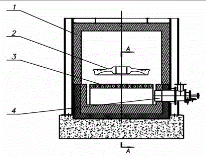
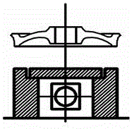
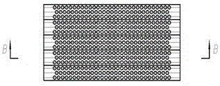
[0030] Such as figure 1 As shown, the heating furnace body 1 adopts light fiber and light bricks as the insulation layer, the workpiece to be heated 2 is suspended in the heating furnace body 1, and the soaking fire insulation box 3 is made of heavy refractory bricks. The side foundation wall is built by standard refractory bricks, and the upper refractory bricks are prefabricated and sintered with low cement castables. There are smoke distribution holes on the refractory bricks, and the high-temperature smoke rises evenly from the smoke distribution holes to heat the workpiece; the air And the gas is sprayed out of the burner after being burned in the combustion chamber of the gas burner 4. The flame is very short at about 200mm, but there is still an open flame sprayed out of the burner to form a bright radiation source, and the high-speed and high-temperature flue g...


PUM


Abstract

The invention discloses a no-open-flame fuel gas uniform-temperature heating device, and belongs to the technical field of heat treatment. The heating device comprises a heating furnace, a fuel gas nozzle and a uniform temperature flame isolation box. The uniform temperature flame isolation box is arranged at the lower portion of the heating furnace and located above the outlet position of the fuel gas nozzle. Smoke distribution holes are evenly distributed in the uniform temperature flame isolation box. The fuel gas nozzle is arranged on the lower furnace wall of the heating furnace. A feeding port is formed in the upper portion of the heating furnace, and through the feeding port, a heated workpiece is placed above the uniform temperature flame isolation box. The uniform temperature flame isolation box is used for isolating flames from the heated workpiece, the flame and high-temperature smoke are diffused after entering the uniform temperature flame isolation box, the high-temperature smoke evenly ascends to heat the heated workpiece, meanwhile, open flames are isolated by the uniform temperature flame isolation box, the heated workpiece cannot be directly exposed to open flame radiation, and therefore the temperature of the workpiece cannot be uneven.

Description

[0001] Technical field: [0002] The invention belongs to the technical field of heat treatment, and in particular relates to a gas uniform temperature heating device without an open flame. [0003] Background technique: [0004] In the heating process of some workpieces, the workpiece is slowly heated at a temperature below 600°C and kept warm for a long time. The workpiece is very sensitive to changes in surface temperature and core temperature. If it is uneven, it will easily cause uneven internal organization of the workpiece, or even become substandard products. At temperatures below 600°C, convective heat transfer is dominant, and radiation heat transfer is supplemented. However, when gas heating is used, the open flame generated by the gas flame becomes a prominent heat radiation source, and the heat radiation intensity of this radiation source is due to the workpiece. The difference in distance and angle is obviously uneven, especially the workpiece moves very slowly. ...

Claims


Application Information

Patent Timeline
Patent Type & Authority Applications(China)
IPC IPC(8): F23D14/02F23D14/48
CPCF23D14/02F23D14/48
Inventor 周炜
Owner HUATIAN ENG & TECH CORP MCC
Learn More