
Air conditioner

A technology for air conditioners and refrigerants, used in refrigerators, compressors, and compressors with reversible cycles, etc., can solve problems such as damage to outdoor unit efficiency, different product performance, and outdoor unit efficiency susceptible to manufacturing deviations. High efficiency and stable high quality, the effect of eliminating influence

Inactive Publication Date: 2017-03-15
HITACHI JOHNSON CONTROLS AIR CONDITIONING INC
View PDF5 Cites 3 Cited by
  • Summary
  • Abstract
  • Description
  • Claims
  • Application Information

AI Technical Summary

Problems solved by technology

Thus, for example, among a plurality of heat exchangers, the respective heat exchangers cannot achieve the same heat exchange performance, so that the efficiency of the outdoor unit is impaired.
In addition, due to the above reasons, the performance of each outdoor unit product is different, resulting in deviations
[0009] That is, in the prior art disclosed in Patent Document 1, there is a problem that the efficiency of the outdoor unit is easily affected by manufacturing variation and individual differences tend to occur.

Method used


Image

  • Air conditioner
  • Air conditioner
  • Air conditioner

Examples


Embodiment 1

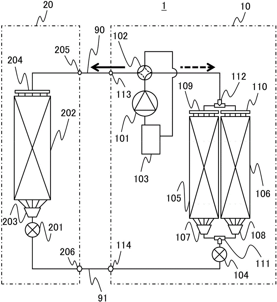
[0028] First, use figure 2 The air conditioner of the present embodiment will be described. figure 2 It is a systematic diagram showing the refrigeration cycle structure of the air conditioner 1 (for example, an example of a commercial air conditioner). exist figure 2 Here, the air conditioner 1 is composed of an outdoor unit 10 , an indoor unit 20 , and pipes 90 and 91 connecting the outdoor unit 10 and the indoor unit 20 .

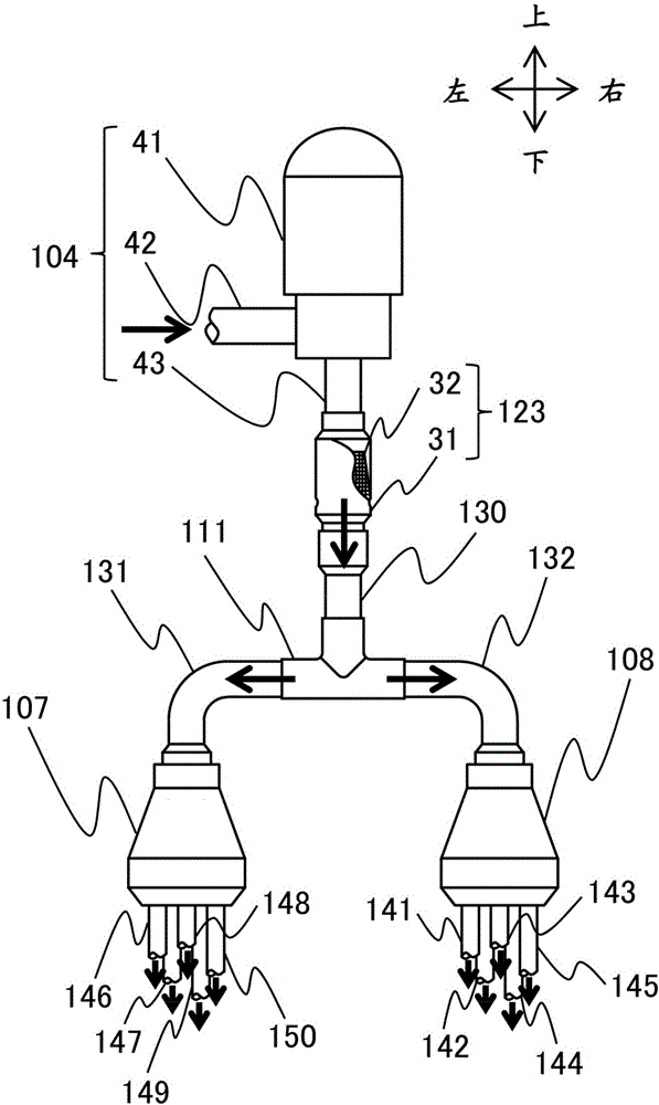
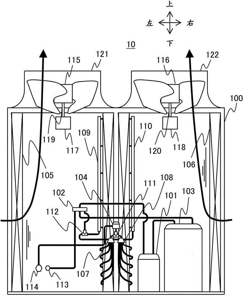
[0029] The outdoor unit 10 includes: a compressor 101 for compressing the refrigerant; a four-way valve 102 for switching the flow direction of the refrigerant; a liquid receiver 103 for separating the refrigerant liquid that has not been evaporated by the evaporator; a device for decompressing the refrigerant. The outdoor expansion valve 104; the outdoor heat exchangers 105 and 106 for exchanging heat between the outside air sent from the outdoor fan (not shown) and the refrigerant; the refrigerant flowing in the outdoor heat exchangers 105 and 106...

Embodiment 2

[0058] In this embodiment, an example in which refrigerant distribution can be adjusted according to the heat exchange capacity of each heat exchanger will be described.

[0059] Figure 7 It is a schematic diagram showing the refrigerant distribution system of this embodiment. exist Figure 7 In , the same reference numerals are assigned to the same components as those in Embodiment 1, and descriptions thereof are omitted, and differences from Embodiment 1 will be mainly described.

[0060] Such as Figure 7 As shown, in this embodiment, a recess 11 is provided on the right lower wall surface of the straight portion of the branch pipe 111b. As a result, the area of ​​the flow path becomes locally small, and the flow resistance increases. Therefore, the flow rate of the refrigerant flowing to the right can be reduced.

[0061] In the outdoor unit, the flow rate of air passing through each heat exchanger is not necessarily the same depending on the arrangement of component...


PUM


Abstract

The air conditioner having an expansion valve for decompressing a refrigerant, and a heat exchanger for heat exchange between the refrigerant and air. The air conditioner includes a first Linearly shaped piping that is connected to the expansion valve and vertically disposed, a branch pipe connected to the first piping for branching a refrigerant flow path into a plurality of sections, a plurality of second pipings connected to the branch pipe, and a plurality of distributors connected to the second piping for further branching the refrigerant flow path to the heat exchanger.

Description

technical field [0001] The present invention relates to air conditioners. Background technique [0002] As one type of outdoor unit used in an air conditioner, there is a so-called up-blown outdoor unit in which air is sucked in from the back and left and right sides by the rotation of a fan installed on the top and blown out upward. [0003] In such an outdoor unit, in order to reduce the size of the unit and improve air blowing and heat exchange performance, it is desirable to expand the front area of ​​the heat exchanger, that is, the circumference and the height, in a priority space. In order to achieve this, there is a method similar to that shown in, for example, Japanese Patent Laid-Open No. 2011-112303 (Patent Document 1). Specifically, it describes that two fans are arranged in parallel on the upper part of the unit, and two heat exchangers formed in a substantially U-shape are arranged so as to surround each fan. Then, headers for branching the refrigerant to the...

Claims


Application Information

Patent Timeline
IPC IPC(8): F25B41/00
CPCF25B41/00F25B13/00F25B39/028F25B2313/005F25B2313/006F25B2313/023F25B2313/02741F25B2500/09F28D1/0477F28F9/0275F25B41/42
Inventor 薛俊上赤匠浦田和干室伏正圭
Owner HITACHI JOHNSON CONTROLS AIR CONDITIONING INC
Learn More