Internal combustion wave rotor gas mixture forming device

An internal combustion wave rotor and wave rotor technology, which is applied in gas turbine devices, jet propulsion devices, machines/engines, etc., can solve the problems of no transition pipe section of the transition pipe device, low economy and practicability, etc., so as to reduce the complexity performance, improve combustion efficiency, and reduce flow loss

Active Publication Date: 2018-12-07
NANJING UNIV OF AERONAUTICS & ASTRONAUTICS
View PDF8 Cites 0 Cited by
  • Summary
  • Abstract
  • Description
  • Claims
  • Application Information

AI Technical Summary

Problems solved by technology

After reviewing related documents and patents, it is found that there is no relevant device that can meet the needs, such as the patent "Wave Rotor Detonation Engine", patent number: US6460342B1 proposes an internal combustion wave rotor device that adopts a detonation combustion mode. The direction is divided into several areas, and each area is fed with different types and components of gas, so that the fuel is distributed in layers in the wave rotor channel. requirements, but the transition pipe section of the transition pipe device does not involve
The patent "Partitioned multi-channel combustor", patent number: US6526936B2, divides the inlet port of the wave rotor along the circumferential direction and the radial direction at the same time, which can control the oil and gas distribution in the wave rotor channel more precisely; it only involves the layered distribution of mixed gas , there is no transition tube device that can be used well for the existing wave rotor engine experimental device
[0003] In addition, the existing wave rotor experimental platform adopts the drive mode of the motor to drive the rotor channel to rotate, which is not economical and practical.

Method used


Image

  • Internal combustion wave rotor gas mixture forming device
  • Internal combustion wave rotor gas mixture forming device
  • Internal combustion wave rotor gas mixture forming device

Examples


Embodiment Construction

[0022] The present invention will be further described below in conjunction with the accompanying drawings and specific embodiments.

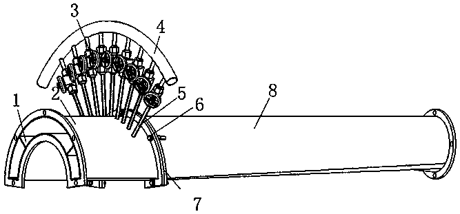
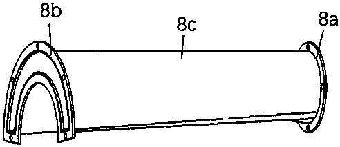
[0023] The structure of the present invention is as figure 1 As shown, it includes the connected transition pipe section 8 and the inlet end section 2 of the wave rotor.

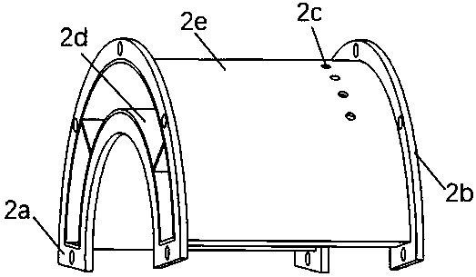
[0024] The structure of the inlet end section 2 of the wave rotor is as follows: figure 2 As shown, it is a cylinder of equal cross section, including an upper wall 2e, a lower wall 2d, a front connecting flange 2a and a rear connecting flange 2b, and its cross section is 170 o Annular cross-section, in which the diameter of the inner ring is 175.2mm, the diameter of the outer ring is 230.8mm, and the circumference angle is 170 o . The inner channel of the wave rotor inlet end section 2 is provided with two deflectors 1, the deflectors 1 divide the wave rotor inlet end section 2 into three inlet areas, and the three inlet areas are filled with different concentrations of ...


PUM


Abstract

The invention provides an internal combustion wave rotor mixed gas generating device. The internal combustion wave rotor mixed gas generating device comprises a transitional pipe segment and a wave rotor gas inlet end segment. Multiple small holes are formed in the upper wall surface of the wave rotor gas inlet end segment. Each small hole is connected with a fuel injection branch pipe. Each fuel injection branch pipe is connected to a fuel inlet header pipe through an independent valve. A channel inside the wave rotor gas inlet end segment is provided with two flow guide plates. The wave rotor gas inlet end segment is divided into three inlet areas by the flow guide plates. The three inlet areas are inflated with mixed gas different in concentration. The internal combustion wave rotor mixed gas generating device has the maximized total pressure recovery coefficient; limited distance transition is achieved; mixed gas can be distributed in a layered manner; and in addition, the flow guide plates can substitute a motor to drive a wave rotor to move.

Description

technical field [0001] The invention relates to the technical field of new concept unsteady combustion, in particular to an internal combustion wave rotor gas mixture forming device. Background technique [0002] Wave rotors, also known as pressure exchangers and energy exchangers, are devices that use unstable waves to exchange energy for airflows with different energy densities, and have the advantage of improving the performance and operating characteristics of various engines and machinery. One of the components of the wave rotor engine, the gas mixture forming device from the outlet of the compressor to the inlet of the wave rotor inlet end plate is one of the key components of the wave rotor engine. The mixed gas forming device of the wave rotor is mainly used for filling the mixed gas of the wave rotor. Considering the requirements of the wave rotor for filling the mixed gas and the transition from the circular cross-section of the outlet of the inlet pipe to the cir...

Claims


Application Information

Patent Timeline
Patent Type & Authority Patents(China)
IPC IPC(8): F02C7/00
CPCF02C7/00
Inventor 李建中李维巩二磊张开晨陈坚李文杰胡阁
Owner NANJING UNIV OF AERONAUTICS & ASTRONAUTICS
Why Eureka
Try Eureka