
Bending die for producing electric box

A bending die and electrical box technology, applied in the field of metal parts processing, can solve problems such as unstable quality, high manufacturing cost, and low processing efficiency, and achieve the effects of simple overall structure, reduced production cost, and improved production efficiency

Inactive Publication Date: 2017-03-15
LITEHARBOR LIGHTING TECHNOLOGY CO LTD
View PDF8 Cites 4 Cited by
  • Summary
  • Abstract
  • Description
  • Claims
  • Application Information

AI Technical Summary

Problems solved by technology

In the production process of the electrical box, two methods are generally used. One is to weld the steel plate or iron plate. Since the electrical box has a high requirement for water resistance, it requires better welding quality and a beautiful appearance. , this method has high production cost and low effect. Another method is to perform bending and forming, because after the four sides of the electrical box are bent, the opening will become smaller. After a set of molds are bent, the tool cannot be withdrawn smoothly, and However, the electrical box needs to be bent on four sides at the same time. However, in the existing production, four sets of molds are required to be bent separately, so the production process is cumbersome, the processing efficiency is low, the manufacturing cost is high, and the quality is not stable.

Method used


Image

  • Bending die for producing electric box
  • Bending die for producing electric box
  • Bending die for producing electric box

Examples


Embodiment Construction

[0023] In order to make the object, technical solution and advantages of the present invention clearer, the present invention will be further described in detail below in conjunction with the accompanying drawings and embodiments. It should be understood that the specific embodiments described here are only used to explain the present invention, not to limit the present invention.

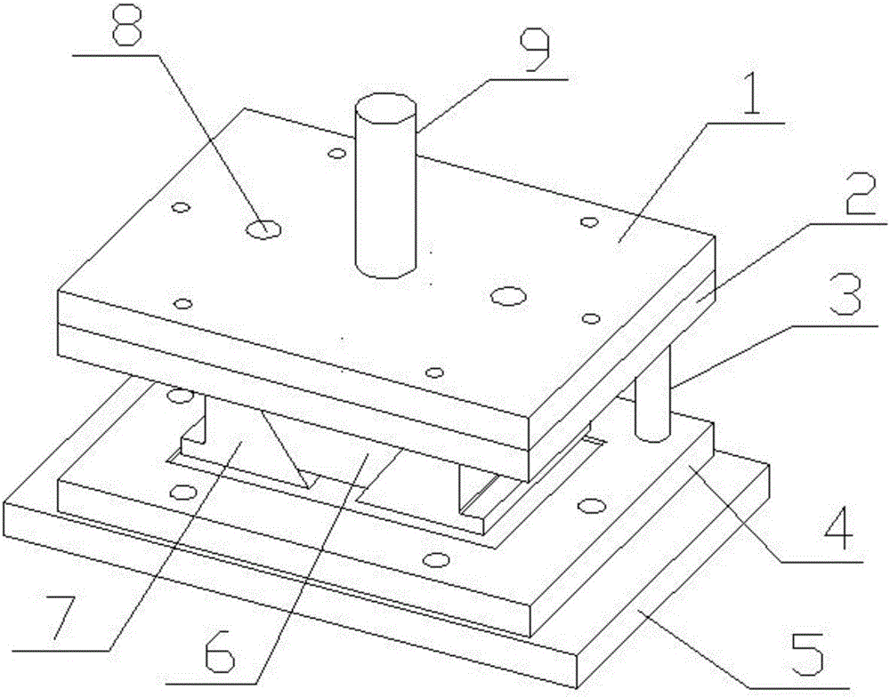
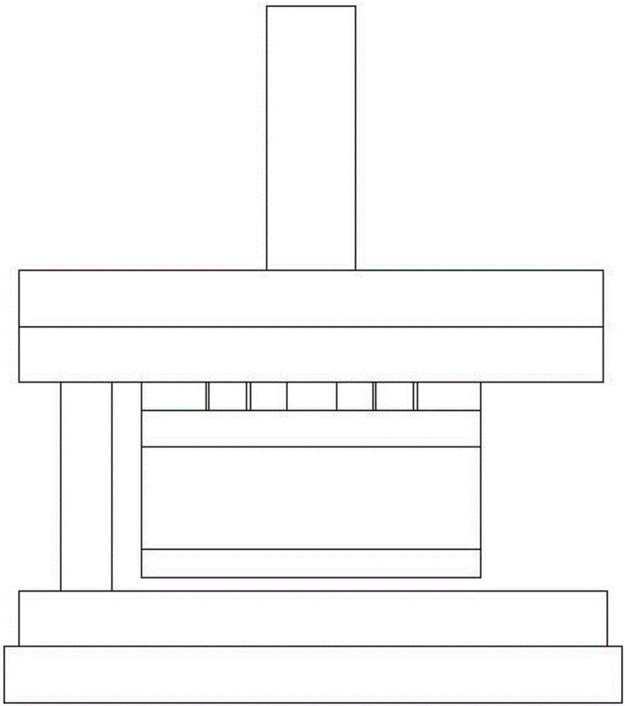
[0024] Such as figure 1 , figure 2 , image 3 , Figure 4 , Figure 5 and Figure 6 As shown, a bending mold for producing electrical boxes includes an upper bending module and a lower bending module, and the upper bending module includes an upper mold base 1 and an upper mold base that are sequentially arranged from top to bottom Die base 2, the top of upper die base 1 is provided with die head post 9, the bottom of upper die base 2 is provided with slide block base 6 and several guide posts 3 that play a guiding role. The bending module and the lower bending module are positioned. The shap...


PUM


Abstract

The invention discloses a bending die for producing an electric box. The bending die comprises an upper bending module and a lower bending module. A sliding block pedestal is arranged at the bottom of an upper die base. Bending sliding blocks are correspondingly arranged on the left side and the right side of the sliding block base. The bending sliding blocks are connected with the upper die base through locating rods. A plurality of sliding chutes are formed in the outer wall on each of the left side and the right side of the sliding block pedestal. Sliding rails are arranged on the outer walls of surfaces, in contact with the sliding block pedestal, of the bending sliding blocks. The sliding block pedestal is connected with the bending sliding blocks through the sliding chutes and the sliding rails. The lower bending module comprises a lower die base and a lower die pedestal, which are arranged in sequence from top to bottom. The bending die is simple in integral structure, and is reasonable in design; the bending sliding blocks are connected with the sliding block pedestal in a sliding manner, and after the four sides of the electric box are bent, a tool can be withdrawn smoothly, in this like, the four sides of the electric box are bent synchronously by using one die, so that the production cost is reduced greatly, the production efficiency is improved, and the product quality is more stable.

Description

technical field [0001] The invention relates to the technical field of metal parts processing, in particular to a bending die for producing electrical boxes. Background technique [0002] With the development of electronic technology, various electronic products are becoming more and more abundant, and there are many places in electronic products that need to use electrical boxes, so the demand for electrical boxes is also increasing. In the production process of the electrical box, two methods are generally used. One is to weld the steel plate or iron plate. Since the electrical box has a high requirement for water resistance, it requires better welding quality and a beautiful appearance. , this method has high production cost and low effect. Another method is to perform bending and forming, because after the four sides of the electrical box are bent, the opening will become smaller. After a set of molds are bent, the tool cannot be withdrawn smoothly, and However, the fou...

Claims


Application Information

Patent Timeline
Patent Type & Authority Applications(China)
IPC IPC(8): B21D37/10B21D5/06
CPCB21D37/10B21D5/06
Inventor 罗垂龙梁兵王鹏程
Owner LITEHARBOR LIGHTING TECHNOLOGY CO LTD
Learn More