
Resistance choke type tiny particle and cell detection micro-fluidic chip and preparation method

A microfluidic chip, flow detection technology, applied in individual particle analysis, chemical instruments and methods, particle and sedimentation analysis, etc., can solve the possibility of increasing multiple particles/cells, damage to detected particles such as cells, detection problems such as low flux, to achieve the effect of increasing the effect, optimizing the structure size parameters, and improving the sensitivity

Active Publication Date: 2017-03-15
SANITARY EQUIP INST ACAD OF MILITARY MEDICAL SCI PLA +1
View PDF6 Cites 28 Cited by
  • Summary
  • Abstract
  • Description
  • Claims
  • Application Information

AI Technical Summary

Problems solved by technology

The disadvantage of such a pipeline is that due to the long pipeline, the flow resistance is relatively large, or the pipeline is relatively wide to reduce the flow resistance, but the detection sensitivity is sacrificed, and the possibility of multiple particles / cells in the detection area is increased; or the pipeline is narrowed, Make the pipe width equal to or even smaller than the outer diameter of particles / cells to improve detection sensitivity, but the flow resistance is too large, the detection flux is very low, and it is easy to block the pipe
If the electrode is far away from the detection site, although the detection sensitivity can be improved by increasing the excitation voltage, the higher voltage may cause damage to the measured particles such as cells.

Method used


Image

  • Resistance choke type tiny particle and cell detection micro-fluidic chip and preparation method
  • Resistance choke type tiny particle and cell detection micro-fluidic chip and preparation method
  • Resistance choke type tiny particle and cell detection micro-fluidic chip and preparation method

Examples


Embodiment Construction

[0061] The solutions of the present invention will be described in detail below in conjunction with the accompanying drawings and specific embodiments.

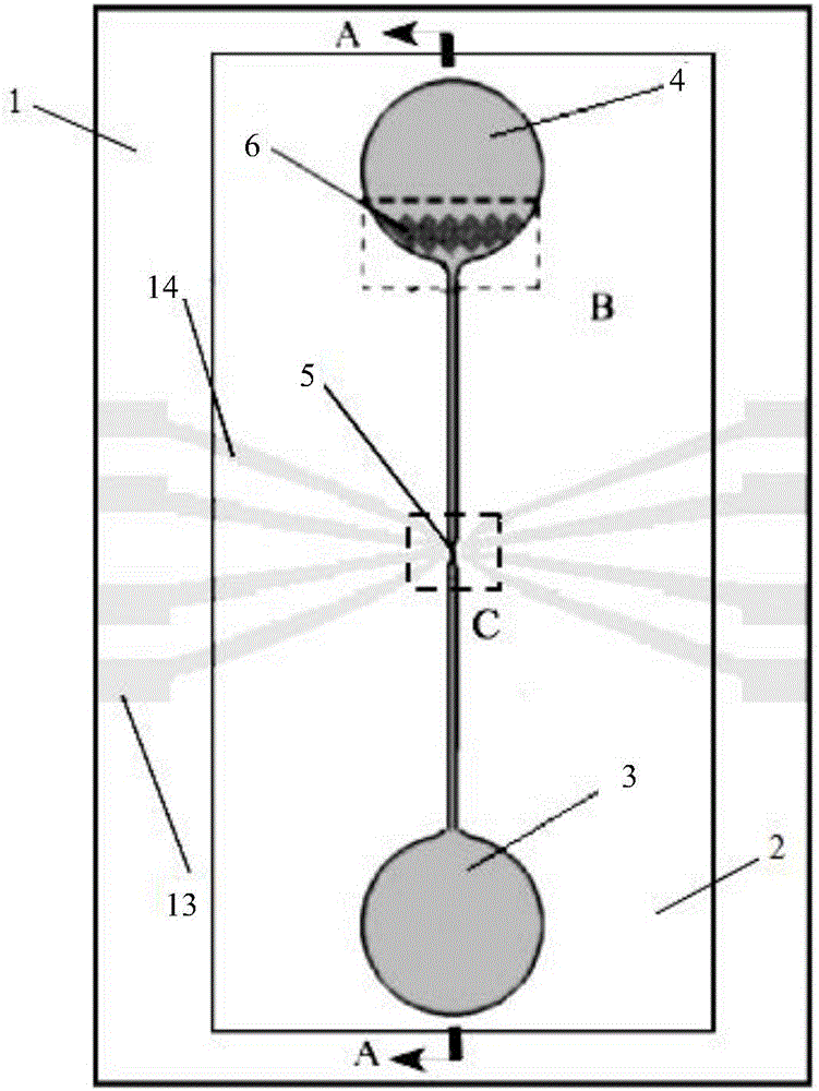
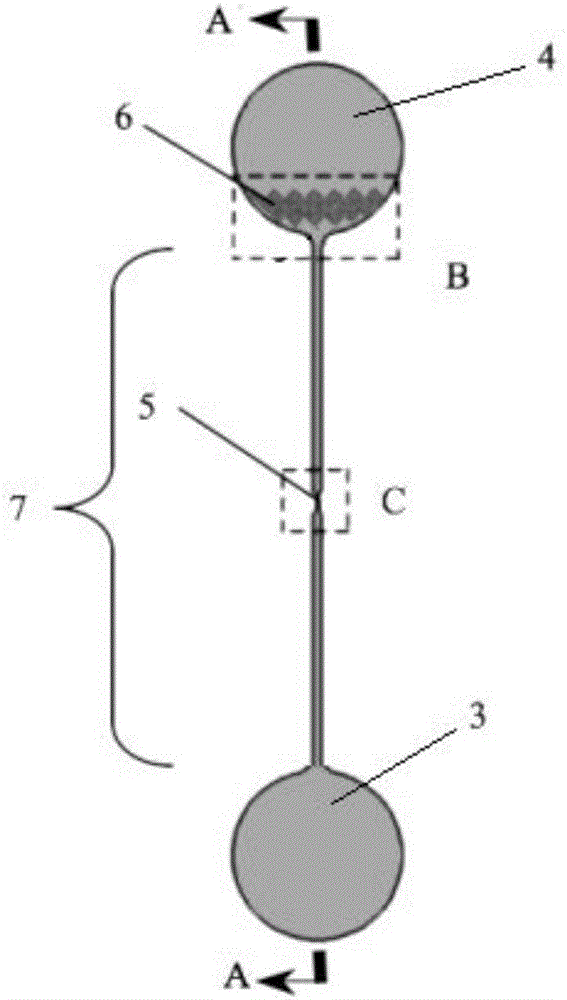
[0062] Such as figure 1 As shown, it is a schematic diagram of the top view structure assembly of the microfluidic chip for the electric impedance flow detection of tiny particles and cells according to a specific embodiment of the present invention. In this example, it is a schematic diagram of the assembly of 8 tiny electrodes.

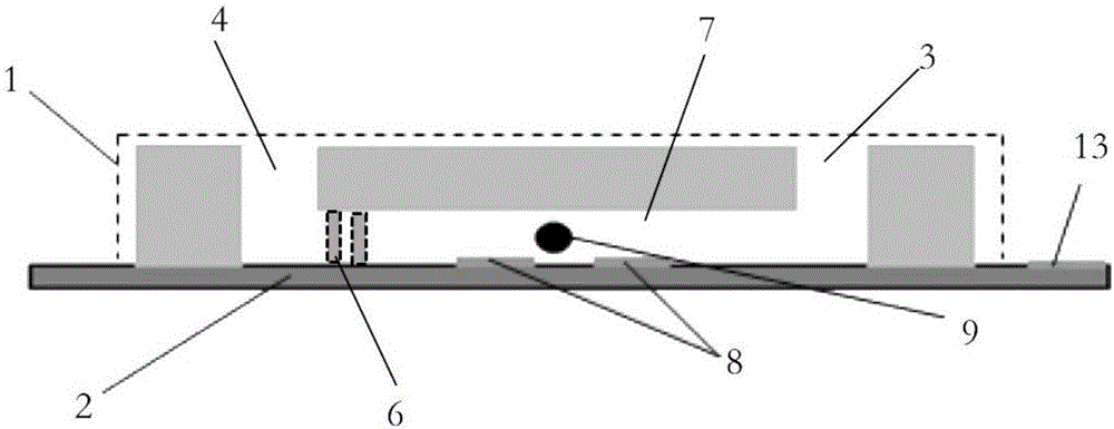
[0063] The tiny electrodes on the substrate are usually made of gold or platinum, but other metals can also be used. The main reason is that the metal is required to have good inertness, and it is not easy to react in the solution when electrified. The micro-electrode is processed by micro-processing technology, and the thickness on the substrate is only tens to hundreds of nanometers, which hardly affects the structural size and fluid flow of the pipeline. The area of ​​the electrode is as small...


PUM


Abstract

The invention discloses a resistance choke type tiny particle and cell detection micro-fluidic chip and a preparation method. A PDMS (polydimethylsiloxane) cover plate (1) and a substrate (2) are bonded to form the resistance choke type tiny particle and cell detection micro-fluidic chip, the shape and the size of the substrate (2) adapt to those of the cover plate, at least one pair of tiny electrodes (8) are arranged on the substrate (2), a micro-fluidic pipeline is arranged on the cover plate, one surface of the substrate (2) with the tiny electrodes and a contact surface of the micro-fluidic pipeline contacting with the substrate are bonded in an aligned manner, the micro-fluidic pipeline is closed and comprises a sample inlet (4), a main pipeline (7) and a sample outlet (3), and the main pipeline (7) is provided with a sample inlet pipeline (10), a shrinkage detection pipeline (11) and the narrowest portion (5). A complex pipeline and fluid control system needed by sheath fluid focusing technology is avoided, flow resistance increase effect caused by pipeline size reduction is avoided by optimized structural size parameters, and detection throughput and sensitivity are improved.

Description

technical field [0001] The invention relates to the technical field of biological cell detection, in particular to a structural design of a microfluidic chip used for micro particle / biological cell detection. Background technique [0002] The traditional Coulter counter uses a direct current signal to detect small particles passing through the micropore in the solution, and it has been developed into an instrument for blood cell analysis. Another device that detects tiny particles / cells is the flow cytometer. Flow cytometry uses optical detection methods to detect particles, which usually require fluorescent labeling of the particles to be tested, while non-labeled detection methods avoid interference and damage to the measured objects. For example, electrical impedance detection is non-labeled detection. kind of. The difference between the method of electrical impedance detection and Coulter counting is mainly that the electrical impedance detection uses an alternating cu...

Claims


Application Information

Patent Timeline
Patent Type & Authority Applications(China)
IPC IPC(8): B01L3/00G01N15/10
CPCB01L3/502707B01L3/502761B01L2200/0668B01L2200/10B01L2200/12B01L2300/0809G01N15/1031G01N2015/1006
Inventor 谢新武程振徐友春田丰徐新喜
Owner SANITARY EQUIP INST ACAD OF MILITARY MEDICAL SCI PLA
Learn More