Novel ultrasonic scaler transducer and scaler handle comprising same
A technology for transducers and dental scalers, which is applied in the fields of cleaning teeth, cleaning methods using liquids, and dentistry. It can solve the problems of complex transducer processing technology and reduce the electromechanical conversion efficiency of transducers, so as to improve electromechanical conversion. Efficiency, achieve insulation, increase the effect of coaxiality
- Summary
- Abstract
- Description
- Claims
- Application Information
AI Technical Summary
Problems solved by technology
Method used
Image
Examples
Embodiment 1
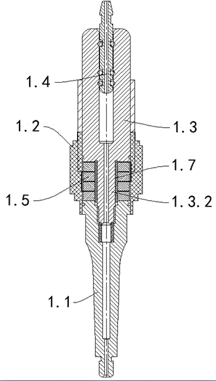
[0015] Such as figure 1 As shown, a new type of ultrasonic scaler transducer, the transducer 1 includes a horn 1.1 at the front end, a piezoelectric ceramic 1.5 at the middle and a main rod 1.3 at the rear end; the front end of the main rod 1.3 is provided with a connecting column 1.3 .2, the rear end of the horn 1.1 is provided with a connection groove 1.1.1; the front end of the connection column 1.3.2 passes through the through hole of the piezoelectric ceramic 1.5 and is sealed with the connection groove 1.1.1; the piezoelectric ceramic 1.5 and A Teflon rigid tube 1.7 for insulation is provided between the connecting columns 1.3.2. The use of Teflon rigid tubes can achieve insulation on the one hand, and increase the coaxiality of the four wafers on the other hand, which greatly improves the electromechanical conversion efficiency of the transducer.
[0016] Further, the end of the Teflon rigid tube 1.7 close to the connection groove 1.1.1 extends into the connection groo...
Embodiment 2
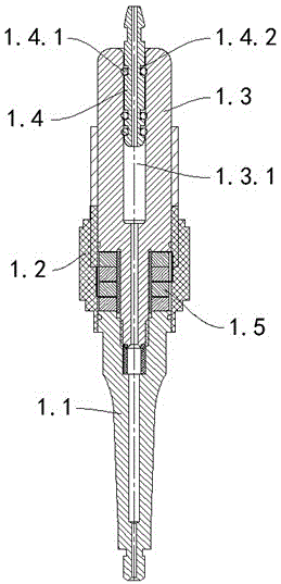
[0021] Such as figure 2 As shown, based on the first embodiment, in order to improve the power of the handle, the present invention also makes a further optimized design, the transducer 1 also includes a metal tube 1.4, and one end of the metal tube 1.4 extends into the main rod 1.3 away from the piezoelectric ceramic 1.5 One end of the connecting hole 1.3.1, and the metal pipe 1.4 and the connecting hole 1.3.1 are connected by a plurality of O-rings 1.4.1, and the O-rings 1.4.1 can be set as two, three or four.
[0022] The present invention improves the connection relationship between the main rod 1.3 of the transducer and the inlay (metal tube 1.4). Specifically, this structure cooperates between a metal water pipe and the main rod 1.3, plus three The O-ring 1.4.1, on the one hand, achieves water passage, and on the other hand, greatly reduces the influence of the water pipe on the performance of the transducer. Ordinary transducer 1 mainly adopts the integral connection ...
Embodiment 3
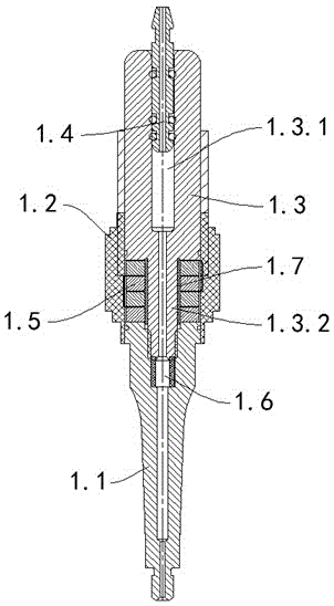
[0027] Such as image 3 As shown, based on the first embodiment, in order to reduce the probability of ignition failure inside the transducer, the present invention also makes a further optimized design. Before the horn 1.1 is connected to the main pole 1.3, a sleeve is added inside the horn 1.1 Barrel 1.6.
[0028] Specifically, a connecting groove 1.1.1 is provided at the rear end of the horn 1.1, and the end of the main rod 1.3 close to the horn 1.1 is provided with a connecting column 1.3.2 extending into the connecting groove 1.1.1; the connecting column 1.3. The front end of 2 passes through the through hole of the piezoelectric ceramic 1.5, and is in sealing connection with the connection groove 1.1.1; It is in conflicting connection with the inner side wall of the connecting groove 1.1.1, and the other end of the sleeve 1.6 is in conflicting connection with the front end of the connecting column 1.3.2.
[0029] The above-mentioned sleeve 1.6 can effectively prevent t...
PUM
| Property | Measurement | Unit |
|---|---|---|
| Length | aaaaa | aaaaa |
| Thickness | aaaaa | aaaaa |
Abstract
Description
Claims
Application Information
 - R&D
- Intellectual Property
- Life Sciences
- Materials
- Tech Scout
- Unparalleled Data Quality
- Higher Quality Content
- 60% Fewer Hallucinations
Browse by: Latest US Patents, China's latest patents, Technical Efficacy Thesaurus, Application Domain, Technology Topic, Popular Technical Reports.
© 2025 PatSnap. All rights reserved.Legal|Privacy policy|Modern Slavery Act Transparency Statement|Sitemap|About US| Contact US: help@patsnap.com


