
Camera calibration method and calibration device

A calibration method and camera technology, applied in image communication, television, electrical components, etc., can solve problems such as overlapping, affecting user experience, blurring certain positions of pictures, etc., to achieve the effect of ensuring the focus effect and improving the shooting experience

Inactive Publication Date: 2019-03-01
上海乐愚智能科技有限公司
View PDF8 Cites 0 Cited by
  • Summary
  • Abstract
  • Description
  • Claims
  • Application Information

AI Technical Summary

Problems solved by technology

However, due to the influence of factors such as production technology and assembly environment, it is difficult to make the lens plane completely perpendicular to the photosensitive plane in actual design. Some parts of the picture will be blurred, affecting the user experience

Method used


Image

  • Camera calibration method and calibration device
  • Camera calibration method and calibration device
  • Camera calibration method and calibration device

Examples


Embodiment Construction

[0023] In order to make the object, technical solution and advantages of the present invention clearer, various embodiments of the present invention will be described in detail below in conjunction with the accompanying drawings. However, those of ordinary skill in the art can understand that, in each implementation manner of the present invention, many technical details are provided for readers to better understand the present application. However, even without these technical details and various changes and modifications based on the following implementation modes, the technical solution claimed in this application can also be realized.

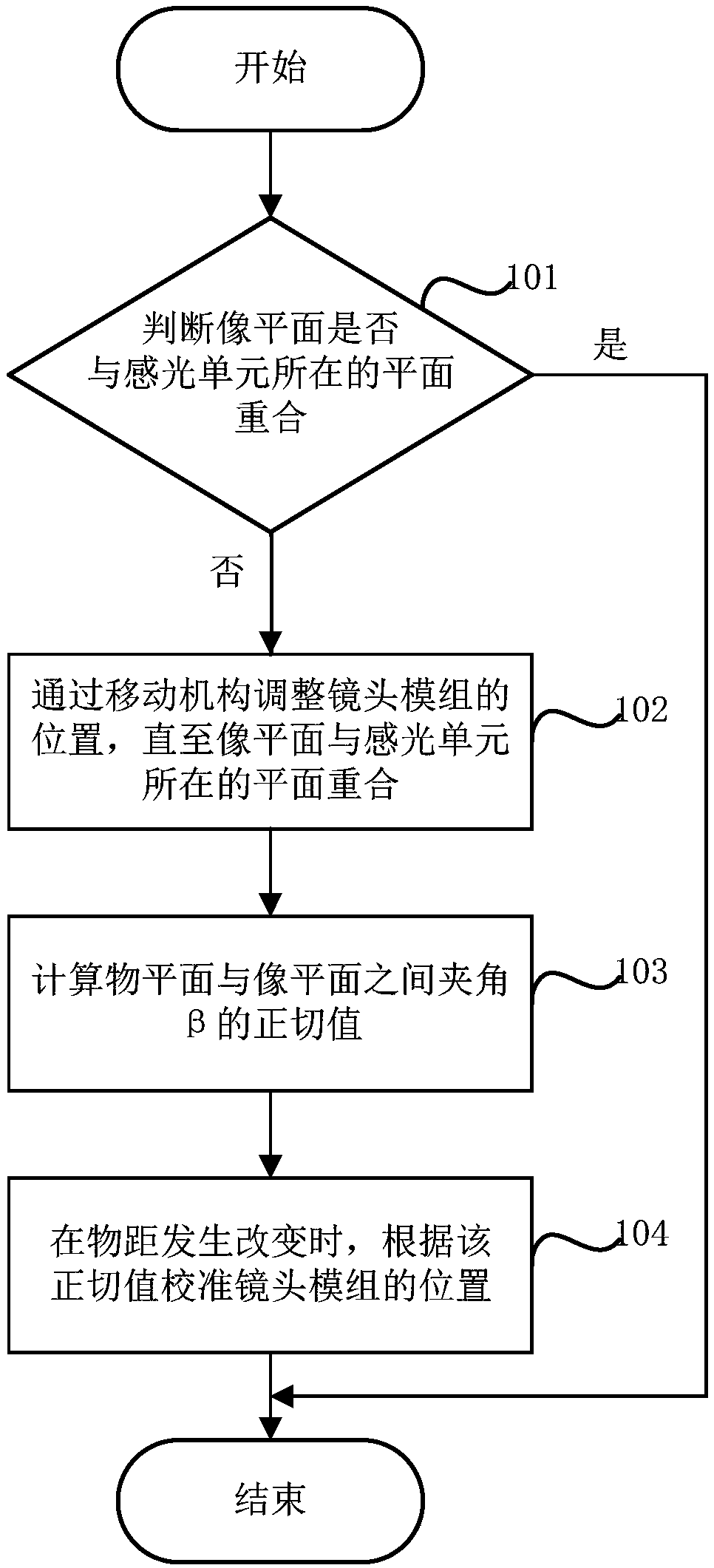
[0024] The first embodiment of the present invention relates to a camera calibration method. The specific process is as figure 1 shown.

[0025] Step 101: Judging whether the image plane coincides with the plane where the photosensitive unit is located, if yes, exit the process; if not, enter step 102.

[0026] The photosensitive unit is...


PUM


Abstract

The invention relates to the technical field of image photographing equipment, and discloses a camera calibration method and a camera calibration device. The calibration method comprises the steps of determining whether an image plane is overlapped with a plane in which a photosensitive unit exists; if not, adjusting the position of a lens module through a moving mechanism until the image plane is overlapped with the plane in which the photosensitive unit exists; on the condition that the image plane is overlapped with the plane in which the photosensitive unit exists, calculating a tangential value of an included angle beta between an object plane and the image plane; and on the condition that an object distance changes, calibrating the position of the lens module according to the tangential value. An embodiment of the invention further discloses a camera calibration device. Compared with prior art, the camera calibration method and the camera calibration device are advantageous in that the position of the lens module can be adjusted through a moving mechanism so that the image plane is overlapped with the plane in which the photosensitive unit exists; and furthermore the tangential value of the included angle between the object plane and the image plane is calculated; and on the condition that the object distance is changed, the position of the lens module can be calibrated according to the tangential value.

Description

technical field [0001] The invention relates to the technical field of camera equipment, in particular to a camera calibration method and a calibration device. Background technique [0002] Along with the popularization of digital photography, a large amount of handheld devices, such as terminal equipments such as mobile phone, player and palmtop computer, are all equipped with camera, to carry out photographing and recording, and utilize camera focus motor to finish focusing during photographing and recording. [0003] In the prior art, the focus motor of the camera is an integrated structure, and the lens is directly installed in the lens carrier. In order to ensure the focusing effect, it is necessary to strictly keep the lens plane perpendicular to the photosensitive plane during installation. Therefore, when focusing, the image plane can coincide with the photosensitive plane, so as to ensure the shooting effect. However, due to the influence of factors such as produc...

Claims


Application Information

Patent Timeline
Patent Type & Authority Patents(China)
IPC IPC(8): H04N17/00
CPCH04N17/002
Inventor 黄俊岚
Owner 上海乐愚智能科技有限公司
Learn More