
Tube and box structure, shell and tube heat exchanger and air conditioner

A tube box and heat exchange tube technology, applied in indirect heat exchangers, heat exchanger types, heat exchanger shells, etc., can solve the problem of reducing heat exchange efficiency, reducing the number of heat exchange tubes, affecting the heat exchange efficiency of shell and tube, etc. problem, to achieve the effect of improving heat exchange efficiency and improving the effect of flow equalization

Active Publication Date: 2018-12-18
GREE ELECTRIC APPLIANCES INC
View PDF6 Cites 0 Cited by
  • Summary
  • Abstract
  • Description
  • Claims
  • Application Information

AI Technical Summary

Problems solved by technology

However, since the refrigerant cannot enter the heat exchange tube evenly, it will affect the heat exchange efficiency of the shell and tube.
Based on this point, the heat exchanger has been improved in the prior art, and a flow equalizer is installed at the inlet of the tube box, but the flow equalizer is fixed on the tube sheet by screws. First, the screws occupy the position of the heat exchange tubes. , leading to a reduction in the number of heat exchange tubes that can be distributed; second, this flow sharing method may lead to uneven conditions such as high velocity in the middle and low velocity on both sides, resulting in problems such as reduced heat exchange efficiency

Method used


Image

  • Tube and box structure, shell and tube heat exchanger and air conditioner
  • Tube and box structure, shell and tube heat exchanger and air conditioner
  • Tube and box structure, shell and tube heat exchanger and air conditioner

Examples


Embodiment Construction

[0023] In order to make the purpose, technical solution and advantages of the present invention clearer, the technical solution of the present invention will be clearly and completely described below in conjunction with specific embodiments of the present invention and corresponding drawings. Apparently, the described embodiments are only some of the embodiments of the present invention, but not all of them. Based on the embodiments of the present invention, all other embodiments obtained by persons of ordinary skill in the art without making creative efforts belong to the protection scope of the present invention.

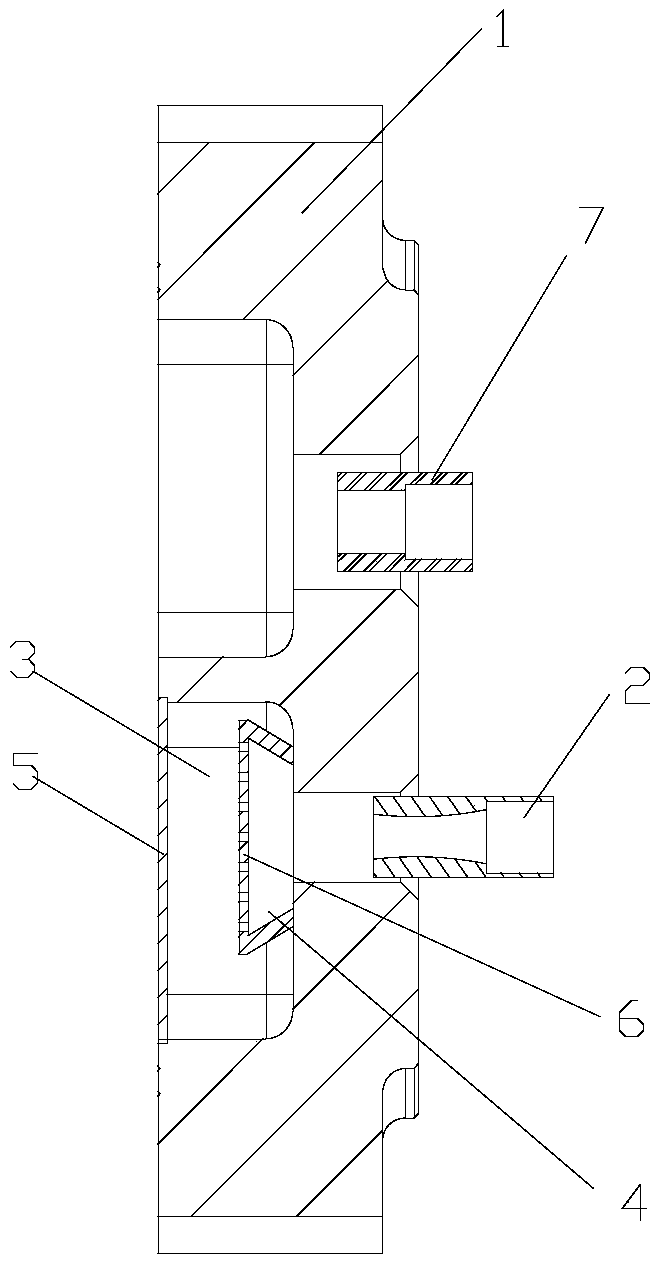
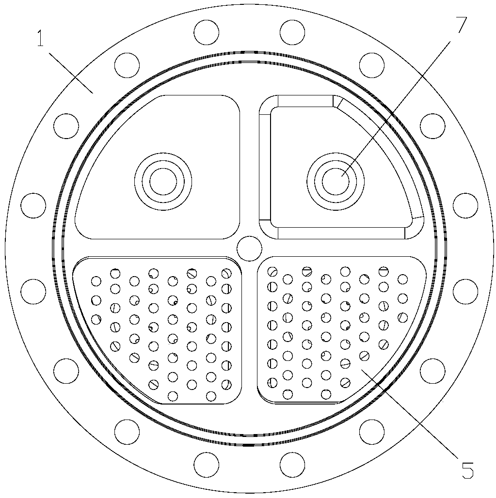
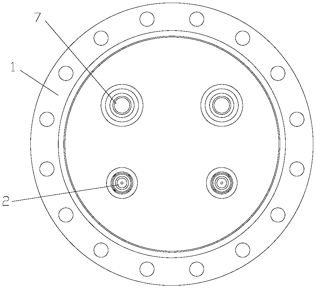
[0024] see in conjunction Figure 1 to Figure 4 As shown, according to the embodiment of the present invention, the pipe box structure includes a housing 1 and a refrigerant liquid inlet connecting pipe 2 connected to the housing 1. The housing 1 is formed with a liquid uniform chamber 3, and a uniform liquid chamber 3 is provided in the liquid uniform chamber 3. ...


PUM


Abstract

The invention provides a tube box structure, a shell and tube heat exchanger and an air-conditioner. The tube box structure comprises a shell (1) and a refrigerant liquid inlet connection pipe (2) connected to the shell (1). A liquid equalizing cavity (3) is formed in the shell (1). A flow equalizing pipe (4) and a first flow equalizing plate (5) located on the outlet side of the flow equalizing pipe (4) are arranged in the liquid equalizing cavity (3). The flow equalizing pipe (4) is connected to the outlet position of the refrigerant liquid inlet connection pipe (2). According to the tube box structure, the flow equalizing effect of the heat exchanger can be improved, and the heat exchange efficiency of the heat exchanger is also improved.

Description

technical field [0001] The invention relates to the technical field of air treatment, in particular to a tube-box structure, a shell-and-tube heat exchanger and an air conditioner. Background technique [0002] At present, in the refrigeration industry, the dry evaporator, as an integral part of the entire refrigeration system, plays a vital role in the entire refrigeration system. However, since the refrigerant cannot uniformly enter the heat exchange tube, the heat exchange efficiency of the shell and tube will be affected. Based on this point, the heat exchanger has been improved in the prior art, and a flow equalizer is installed at the inlet of the tube box, but the flow equalizer is fixed on the tube sheet by screws. First, the screws occupy the position of the heat exchange tubes. , leading to a reduction in the number of heat exchange tubes that can be distributed; second, this flow sharing method may lead to uneven conditions such as high velocity in the middle and...

Claims


Application Information

Patent Timeline
Patent Type & Authority Patents(China)
IPC IPC(8): F28D7/16F28F9/02F28F9/22F25B39/02F24F13/30
CPCF24F13/30F25B39/02F25B2500/09F28D7/16F28F9/02F28F9/22
Inventor 胡东兵杨威胡海利
Owner GREE ELECTRIC APPLIANCES INC
Learn More