
Combustor provided with integral fire cover

A kind of burner, integrated technology, applied in the direction of gas fuel burner, burner, combustion method, etc., can solve the problem of weak flame heating, etc., achieve the effect of uniform combustion temperature field, enlarged heating range, and strong impact of viewing angle

Inactive Publication Date: 2017-03-08
吴成年 +1
View PDF8 Cites 2 Cited by
  • Summary
  • Abstract
  • Description
  • Claims
  • Application Information

AI Technical Summary

Problems solved by technology

[0002] On existing gas stoves, the fire cover of the burner is mostly composed of a large fire cover in the outer ring and a small fire cover in the center, and the large and small fire covers are independent of each other; the setting of the fire holes on the fire cover is mostly concentrated on the circumference of the fire cover On, or on the top surface of the fire cover, between the large and small fire covers, there is a weak area heated by the flame because it is impossible to set the fire hole on the fire cover

Method used


Image

  • Combustor provided with integral fire cover
  • Combustor provided with integral fire cover
  • Combustor provided with integral fire cover

Examples


Embodiment 1

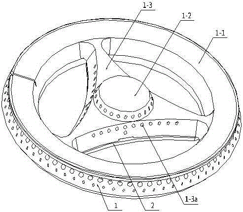
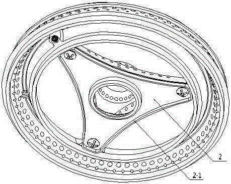
[0029] A burner equipped with an integral fire cover at least includes a burner main body and a large and small fire cover. The integral fire cover at least includes a fire cover main body 1 and a fire cover seat 2. The fire cover main body includes Between the large fire cover 1-1 and the small fire cover 1-2, there are three spokes 1-3, which connect the large and small fire covers as a whole. -6 connected cavities 1-5, the spokes are provided with several fire holes 1-3a to communicate with the cavity; the main body of the fire cover is provided with a fire cover seat mounting surface 1-4, and 3 threaded mounting surfaces are provided. Hole 1-4a, the central part of the fire cover seat is provided with an opening, and the periphery is provided with 3 mounting holes, and the fire cover seat and the fire cover body are connected as a whole through a threaded connection structure;

[0030] The spokes on the main body of the fire cover in this embodiment have a small outer end ...

Embodiment 2

[0033] Such as Figure 7-8 As shown, the only difference between this embodiment and Embodiment 1 is that the top surface of the spokes on the main body of the fire cover is flush with the top surface of the fire cover.

Embodiment 3

[0035] Such as Figure 9 As shown, the difference between this embodiment and Embodiment 1 is that the outer end of the spokes on the main body of the fire cover is placed on the top surface of the large fire cover, the top of the small fire cover is arc-shaped, and the installation surface of the fire cover seat on the fire cover main body is in line with the implementation The shape of example 1 is somewhat different, and the shape of the fire cover seat also changes thereupon.


PUM


Abstract

The invention discloses a combustor provided with an integral fire cover. The combustor at least comprises a combustor main body, a large fire cover and a small fire cover; the integral fire cover at least comprises a fire cover main body and a fire cover seat; three spokes are arranged between the large fire cover and the small fire cover of the fire cover main body to connect the large fire cover and the small fire cover into an integer; a cavity communicating with the inner cavity of the small fire cover in the center is arranged below the spokes; fire holes communicating with the cavity are formed in two sides of the spokes; the fire cover main body is provided with a fire cover seat mounting surface in which mounting holes with screw threads are formed; an open hole is formed in the center of the fire cover seat, and mounting holes are formed in the periphery of the fire cover seat; and the fire cover seat is connected with the fire cover main body into an integer through a threaded connecting structure. Not only can the thermal efficiency and combustion performance of the combustor be remarkably improved, but also the appearance is novel and attractive, the visual impact is very strong, a Benz-logo series fire cover and the like can be formed; and the combustor is convenient to dismount and mount and beneficial to cleaning and maintenance.

Description

technical field [0001] The invention relates to a burner for a gas range, in particular to a burner equipped with an integral fire cover. Background technique [0002] On existing gas stoves, the fire cover of the burner is mostly composed of a large fire cover in the outer ring and a small fire cover in the center, and the large and small fire covers are independent of each other; the setting of the fire holes on the fire cover is mostly concentrated on the circumference of the fire cover On, or on the top surface of the fire cover, between the large and small fire covers, there is a weak zone heated by the flame because the fire hole cannot be set on the fire cover. The size of the fire hole area on the small fire cover and the distribution of the fire hole position have a very important influence on the combustion performance and thermal efficiency of the burner. [0003] Can the distribution of fire holes on the central small fire cover be more conducive to improving th...

Claims


Application Information

Patent Timeline
Patent Type & Authority Applications(China)
IPC IPC(8): F23D14/00F23D14/46
Inventor 吴成年
Owner 吴成年
Learn More