Novel belt conveyor tail automatic moving device

A belt conveyor and self-moving technology, which is applied in transportation and packaging, earth drilling, underground transportation, etc., can solve the problems of inconvenient transportation, small selection of profiles, and easy loss, etc., to achieve convenient and flexible disassembly and transportation, and reduce installation link, to ensure the overall effect

Inactive Publication Date: 2017-03-08
苏士清
View PDF10 Cites 0 Cited by
  • Summary
  • Abstract
  • Description
  • Claims
  • Application Information

AI Technical Summary

Problems solved by technology

[0002] At present, the belt conveyor tail self-moving and pushing device (self-moving tail) in the coal mine is used for the self-moving of the trough transfer machine in the fully mechanized mining face and the overlapping of the tail of the belt conveyor, which can meet the needs of high-yield and high-efficiency working faces. However, in practical applications, due to the complicated underground geological structure conditions, large changes in the roof and floor, and the fast self-moving and moving device of the belt tail, it is inconvenient to transport, resulting in a large amount of roadway maintenance, and There are many links in the installation and connection, and the workload is heavy. Due to the use of many parts, it is easy to lose during the installation and removal process. At the same time, the selection of profiles used is small and the strength is low. The heavy-duty transfer machine walks on it, and when the tail of the towing machine It is easy to make the track and the rack become obsolete, and to solve the above problems, a new technical solution is provided

Method used


Image

  • Novel belt conveyor tail automatic moving device
  • Novel belt conveyor tail automatic moving device
  • Novel belt conveyor tail automatic moving device

Examples


Embodiment Construction

[0011] The technical solutions in the embodiments of the present invention will be clearly and completely described below in conjunction with the accompanying drawings in the embodiments of the present invention.

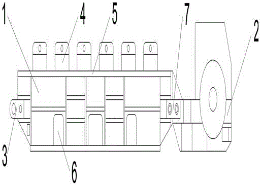
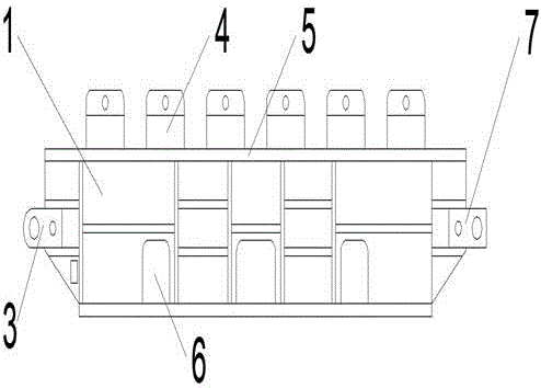
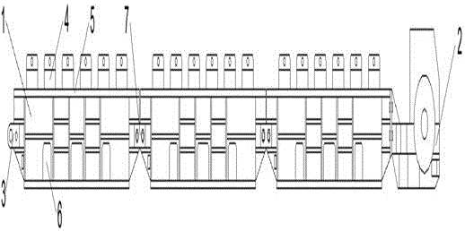
[0012] like Figure 1-3 As shown, a new type of belt conveyor tail self-moving device includes several frames 1 and reel seats 2. The frame 1 is provided with traction connecting ears 3, buffer idler groups 4, sports car tracks 5, and observation and flushing ports. 6 and the connecting plate 7, the traction connecting ear 3 is set on both sides of the front end of the frame 1, the buffer roller group 4 is set on the top of the frame 1, the sports car track 5 is set on both sides of the top of the frame 1, and the observation flushing port 6 is set on the machine frame On both sides below the frame 1, connecting plates 7 are arranged on both sides of the rear end of the frame 1, the reel seat 2 is connected to the rear end of the frame 1, and the reel seat 2 is conn...


PUM


Abstract

The invention discloses a novel belt conveyor tail automatic moving device which comprises a plurality of racks and a winding drum seat. Traction connecting lugs, a buffer supporting roller group, cart running rails, observing and flushing ports and connecting plates are arranged on the racks, the traction connecting lugs are arranged on two sides of the front ends of the racks, the buffer supporting roller group is arranged above the racks, the cart running rails are arranged on two sides above the racks, the observing and flushing ports are arranged on two sides below the racks, the connecting plates are arranged on two sides of the rear ends of the racks, and the winding drum seat is connected to the rear ends of the racks and is in bolt connection with the connecting plates. The novel belt conveyor tail automatic moving device is large in transport capacity, small in resistance, low in energy consumption and flexible in extension and contraction, and is high in working face advancing speed and large in transport distance conversion during fully-mechanized coal mining.

Description

technical field [0001] The invention relates to a novel belt conveyor tail self-moving device, which belongs to the technical field of mining equipment. Background technique [0002] At present, the belt conveyor tail self-moving and pushing device (self-moving tail) in the coal mine is used for the self-moving of the trough transfer machine in the fully mechanized mining face and the overlapping of the tail of the belt conveyor, which can meet the needs of high-yield and high-efficiency working faces. However, in practical applications, due to the complicated underground geological structure conditions, large changes in the roof and floor, and the fast self-moving and moving device of the belt tail, it is inconvenient to transport, resulting in a large amount of roadway maintenance, and There are many links in the installation and connection, and the workload is heavy. Due to the use of many parts, it is easy to lose during the installation and removal process. At the same ...

Claims


Application Information

Patent Timeline
Patent Type & Authority Applications(China)
IPC IPC(8): E21F13/08
CPCE21F13/08
Inventor 陈波郭仁光刘延芳吴玉侠张维维蒋兴凯阮可陈鹏苏士清
Owner 苏士清
Why Eureka
Try Eureka