
A battery sealing laser welding equipment

A laser welding and battery technology, applied in laser welding equipment, welding equipment, welding equipment and other directions, can solve the problems of poor welding stability, scrapped welding products, large product differences, etc., achieve fast welding speed, prevent welding oxidation, improve The effect of production efficiency

Active Publication Date: 2019-01-22
SHENZHEN KINGBEFOUND LASER TECH CO LTD
View PDF11 Cites 2 Cited by
  • Summary
  • Abstract
  • Description
  • Claims
  • Application Information

AI Technical Summary

Problems solved by technology

[0003] In the prior art laser welding equipment for the top cover of lithium batteries, the mechanical positioning fixture is positioned on both sides and the bottom is kept fixed. In the actual process, because there is a certain height difference between each battery, if the bottom is kept fixed, the height of the top cover will be Correspondingly, there will be a certain height difference. The existence of this height difference will easily cause the position deviation of the battery during the laser welding of the top cover, resulting in large product differences and poor welding stability, which will seriously cause the welding product to be scrapped.

Method used


Image

  • A battery sealing laser welding equipment
  • A battery sealing laser welding equipment
  • A battery sealing laser welding equipment

Examples


Embodiment Construction

[0036]The present invention will be further described below in conjunction with the accompanying drawings and specific embodiments. Terms such as "upper", "lower", "left", "right", "middle" and "one" quoted in the preferred embodiment are only for convenience of description, and are not used to limit the scope of the present invention. The scope of implementation and the change or adjustment of its relative relationship shall also be regarded as the scope of implementation of the present invention without substantive changes in technical content.

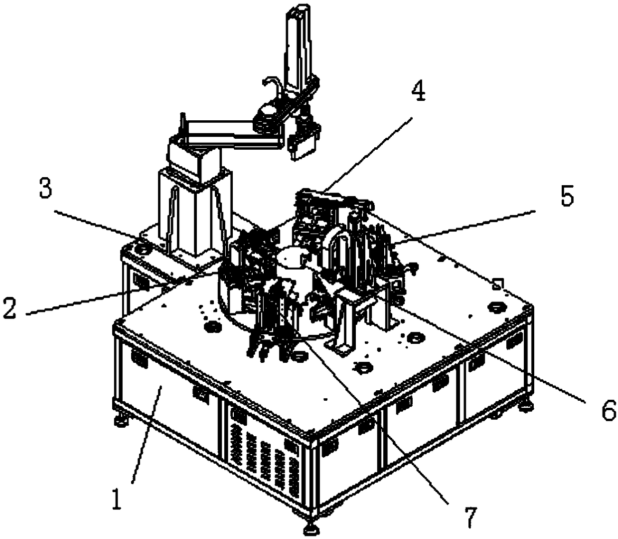
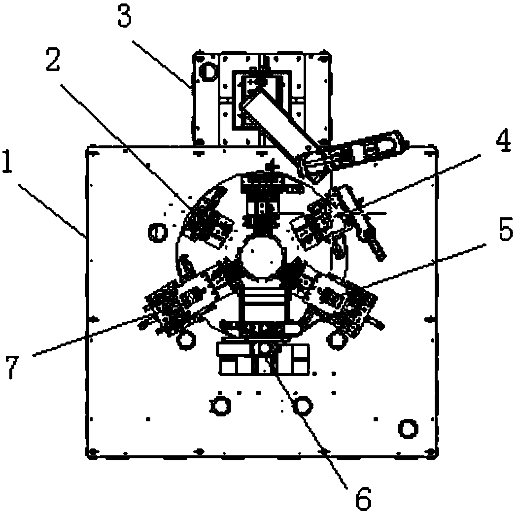
[0037] figure 1 A structural schematic diagram of an example provided for the battery sealing laser welding equipment of the present invention, figure 2 for the invention figure 1 top view in , Figure 6-1 It is a structural diagram of the laser welding mechanism of the present invention, Figure 6-2 It is a side view of the laser welding mechanism of the present invention.

[0038] like figure 1 , figure 2 , Figure 6-1 a...


PUM


Abstract

The invention discloses a laser welding device for battery sealing. The laser welding device comprises a worktable, a rotary disc assembly, a carrying mechanical arm mechanism, a pressing height measuring mechanism, a protection cover containing mechanism, a laser welding mechanism and a protection cover demounting mechanism. The rotary disc assembly comprises a rotary disc and a divider. Six stations are sequentially and evenly arranged on the rotary disc around the circle center of the rotary disc, wherein the included angle of every two connected stations is 60 degrees, and each station is provided with a mechanical positioning clamp. The carrying mechanical arm mechanism, the pressing height measuring mechanism, the protection cover containing mechanism, the laser welding mechanism and the protection cover demounting mechanism are sequentially installed on the tabletop of the worktable around the edge of the rotary disc and in the rotating direction of the rotary disc and each correspond to one station of the rotary disc. The laser welding mechanism comprises an installation supporting plate, a module installation vertical plate, a CCD vision positioning and recognizing assembly, a linear module and a laser device. Air knife supports are arranged at the positions, located on the two sides of the laser device, of the installation supporting plate. An inclined opening air knife is erected at the front end of each air knife support. According to the laser welding device for battery sealing, the welding efficiency and the qualification rate of battery top covers are improved.

Description

technical field [0001] The invention relates to the technical field of laser galvanometer welding equipment, in particular to a battery sealing laser welding equipment. Background technique [0002] The battery manufacturing process involves a wide range of welding techniques, such as ultrasonic welding, resistance welding and laser welding. The reasonable selection of welding methods and processes directly affects the production cost, quality reliability and safety of the battery. As a very important process link in battery production, laser welding has a great impact on the consistency, stability and safety of the battery. There are many laser welding parts of the battery, the process is difficult, and the welding process is more demanding. [0003] In the laser welding equipment for the top cover of lithium batteries in the prior art, the mechanical positioning fixture is positioned on both sides and the bottom is kept fixed. In the actual process, because there is a cer...

Claims


Application Information

Patent Timeline
Patent Type & Authority Patents(China)
IPC IPC(8): B23K26/21B23K26/70B23K26/03B23K26/142B23K37/04
CPCB23K26/032B23K26/142B23K26/21B23K26/702B23K37/0435
Inventor 覃晓鸣李卫星
Owner SHENZHEN KINGBEFOUND LASER TECH CO LTD
Learn More