Eureka AIR delivers breakthrough ideas for toughest innovation challenges, trusted by R&D personnel around the world.
A kind of toner pipeline dredging device
What is Al technical title?
Al technical title is built by PatSnap Al team. It summarizes the technical point description of the patent document.
A pipeline and carbon gun technology, which is applied in the field of toner pipeline dredging devices, can solve the problems of slow drop of negative pressure pressure, failure to dredging pipelines successfully, reducing dredging effect, etc., so as to improve efficiency and success rate, and ensure dredging effect and quality. , the effect of low price
Active Publication Date: 2019-03-29
BAOSHAN IRON & STEEL CO LTD
View PDF6 Cites 0 Cited by
Summary
Abstract
Description
Claims
Application Information
AI Technical Summary
This helps you quickly interpret patents by identifying the three key elements:
Problems solved by technology
Method used
Benefits of technology
Problems solved by technology
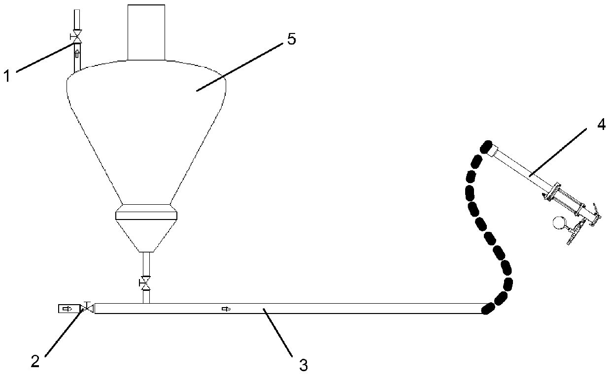
[0005] According to experience, most of the blockages occur near the carbon gun 4. Since the discharge valve 1 and the blockage are usually separated by 50 meters to 60 meters, too long a distance causes the pressure of 0.6Mpa delivered by the compressed air 2 to the pipeline. The long build-up time not only reduces the dredging efficiency, but more importantly, the excessively long distance causes the negative pressure generated instantly when the discharge valve 1 is opened to drop slowly, which directly reduces the dredging effect
Therefore, it is often impossible to successfully unblock the pipeline. At this time, the pipeline close to the 4th end of the carbon gun can only be disassembled to find the blockage point and manually unblock it. This method is time-consuming and laborious. It is necessary to disassemble each section of the pipeline flange, which will cause downtime
Method used
Image
Click on the blue label to locate the original text in one second.
Reading with bidirectional positioning of images and text.
Examples
Embodiment Construction
[0027] The technical solutions of the present invention will be further described below in conjunction with the accompanying drawings and embodiments.
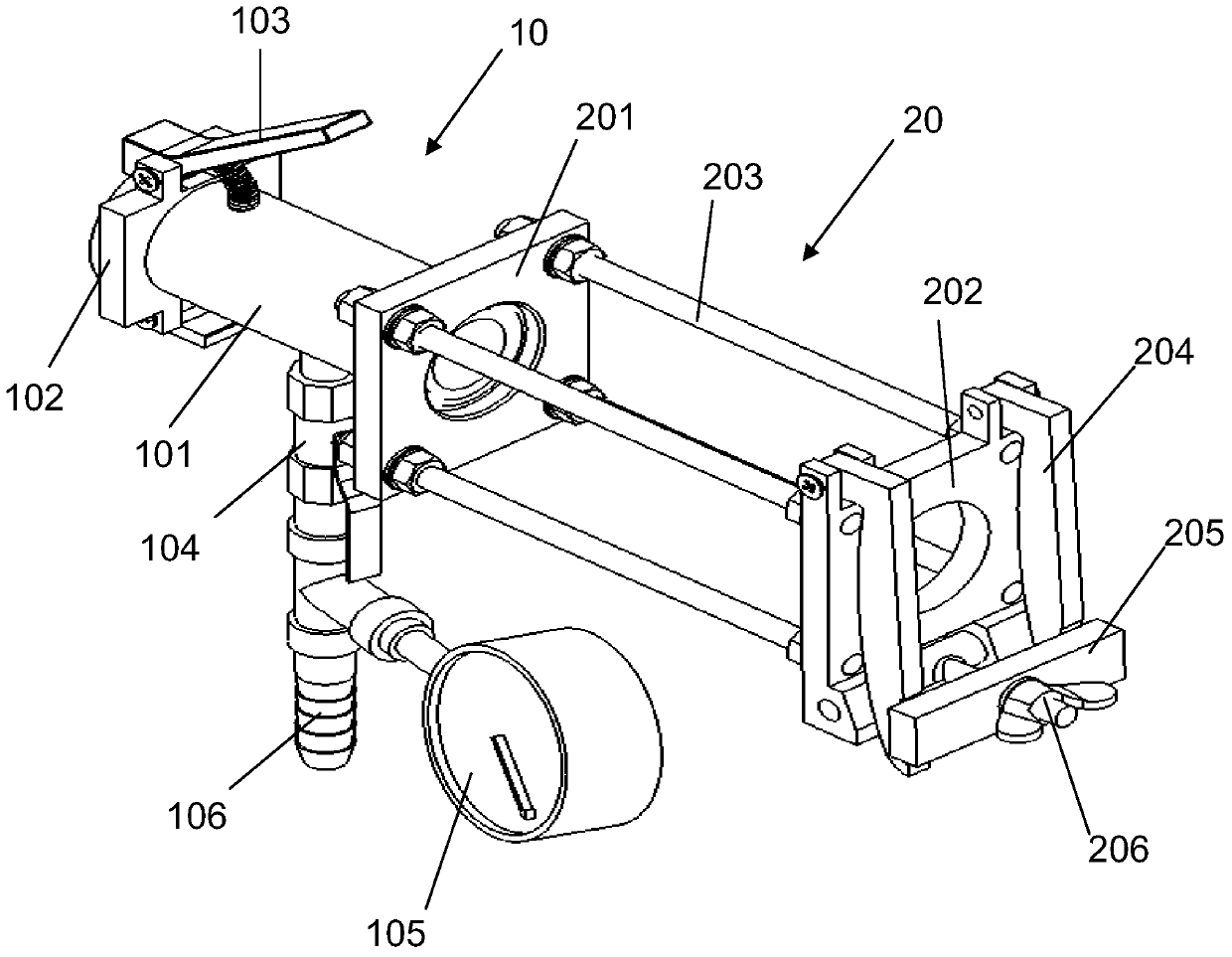
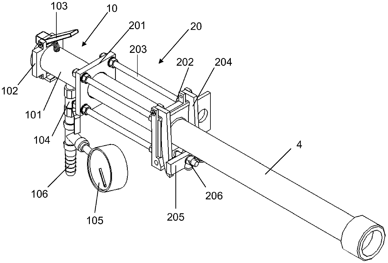
[0028] combine Figures 2 to 6 As shown, the present invention includes a clamping mechanism 20 and a release mechanism 10, the clamping mechanism 20 is used to clamp the movable end of the carbon gun, and the release mechanism 10 includes a release cavity 101, an end cover 102, a spring pressure rod 103, and the release cavity The front end of 101 is fixedly connected with the clamping mechanism 20 and communicated with the carbon gun. The end cover 102 is movable at the rear end of the release cavity 101, and the spring pressure rod 103 is pressed on the top of the end cover 102, and is used to control the opening and closing of the end cover 102 to release The cavity 101 is also communicated with a compressed air inlet branch pipe.
[0029] Described clamping mechanism 20 comprises mounting frame and clamping part, and mou...
PUM
Abstract
The invention discloses a pipeline dredging device. Through the device, one end of a carbon gun of a carbon powder pipeline is clamped, a ball valve is opened to input compressed air into the carbon powder pipeline, after a pressure gage displays that the pressure rises to the system pressure, the ball valve is closed, a pressing rod is pressed, pressure in the pipeline ejects an end cover open, carbon powder is brought out of the pipeline, the end cover is closed, the ball valve is opened, the compressed air is input again, and through repeated implementation of the above steps, the pipeline can be successfully dredged; through the device, the positive and negative pressure difference alternative dredging of any connecting point of the pipeline can be achieved, rapid loading and unloading and the carbon powder pipeline dredging work can be completed only through one person, the dredging efficiency and the success rate are improved, the shutdown overhauling time is shortened, the dredging effect and quality are ensured, involved parts are common spare parts in equipment management, the cost is low, material taking is convenient, mounting is convenient, detection is reliable, and maintaining is easy.
Description
technical field [0001] The invention relates to a pipeline dredging device, more specifically, to a toner pipeline dredging device. Background technique [0002] The ultra-high power DC electric arc furnace of the electric furnace factory adopts the "submerged arc" smelting technology of foam slag. Its technological feature is to cover the arc by generating foamy slag, which not only improves the thermal efficiency in the furnace, reduces power consumption and shortens the smelting cycle, but also reduces the possibility of damage to refractory materials and water-cooled furnace walls caused by arc light scattering. During smelting, only by stably injecting carbon powder can the carbon-oxygen reaction in the furnace be maintained, and finally the effective generation of foamy slag can be realized. [0003] Restricted by the plant structure and equipment layout, there is a long distance from the toner storage bin to each carbon injection point, so that a single toner pipelin...
Claims
Application Information
Patent Timeline
Application Date:The date an application was filed.
Publication Date:The date a patent or application was officially published.
First Publication Date:The earliest publication date of a patent with the same application number.
Issue Date:Publication date of the patent grant document.
PCT Entry Date:The Entry date of PCT National Phase.
Estimated Expiry Date:The statutory expiry date of a patent right according to the Patent Law, and it is the longest term of protection that the patent right can achieve without the termination of the patent right due to other reasons(Term extension factor has been taken into account ).
Invalid Date:Actual expiry date is based on effective date or publication date of legal transaction data of invalid patent.