Centrifugal automatic oil sludge separation machine

A sludge separation and centrifugal technology, applied in the separation of sediment by centrifugal force, separation method, sedimentation separation, etc., can solve the problems of high cost, inconvenient installation, low degree of automation, etc., to improve product quality, ensure wire drawing speed, cleanliness The effect of increasing the degree of

Active Publication Date: 2017-03-08
武汉电缆有限公司
View PDF11 Cites 1 Cited by
  • Summary
  • Abstract
  • Description
  • Claims
  • Application Information

AI Technical Summary

Problems solved by technology

Disadvantages are: high price, unit price between 150,000 and 250,000 yuan, large size, inconvenient installation, not suitable for our company
The disadvantages are: low efficiency, unable to realize automatic slag discharge, low degree of automation
Disadvantages are: the cost of later use is high, the filter cloth is often changed, and it is inconvenient to use

Method used


Image

  • Centrifugal automatic oil sludge separation machine
  • Centrifugal automatic oil sludge separation machine
  • Centrifugal automatic oil sludge separation machine

Examples


Embodiment Construction

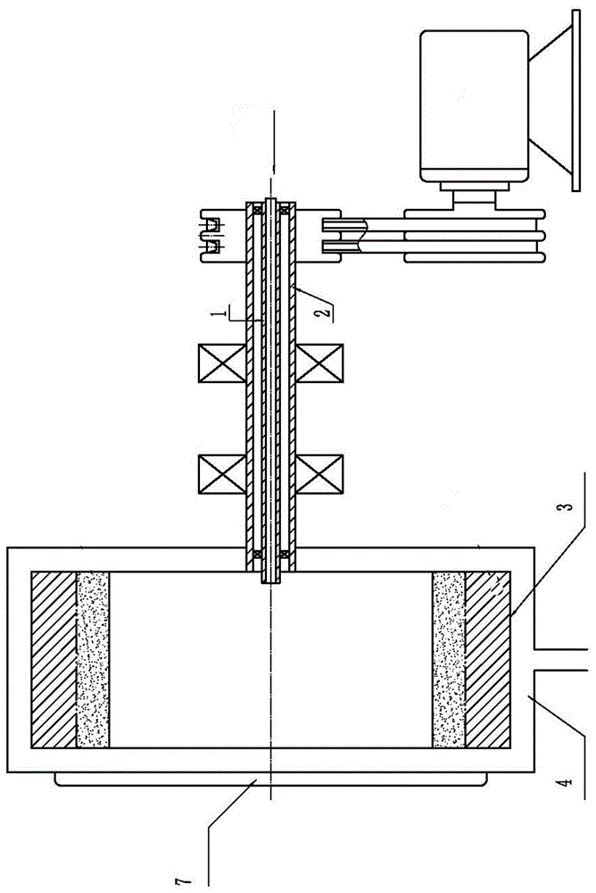
[0051] root tree figure 1 — Figure 4 As shown, a centrifugal automatic sludge separator includes a horizontal drum 3, a protective cover 4 is arranged outside the horizontal drum, the horizontal drum 3 is connected to the power center hollow shaft 2 at one end, and the dirty oil delivery pipe 1 is installed at both ends. Bearings are installed in the hollow shaft 2 of the power center, and the transmission on the hollow shaft 2 of the power center is connected with the power machine. The safety door of the horizontal drum 3 is equipped with a stepping oil scraping device 5 and a stepping scraper shoveling device 6 .

[0052] The protective cover includes a cover body and a safety door.

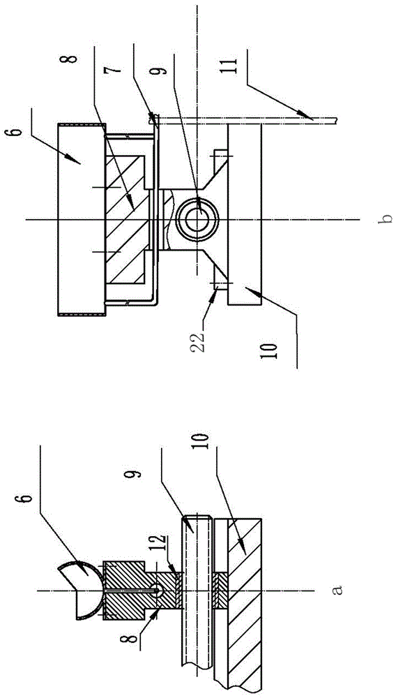
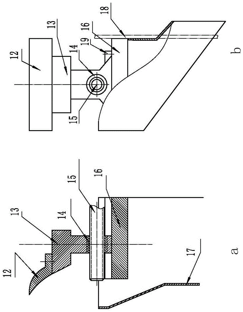
[0053]The stepping oil scraping device includes: the oil scraping groove 6 is connected with the mobile bracket 8, the screw nut 12

[0054] Link to each other with the hole of mobile support 8, screw mandrel 9 and screw nut 12 link to each other, oil guide pipe 7 is arranged in the mobile...


PUM


Abstract

The invention discloses a centrifugal automatic oil sludge separation machine. The oil sludge separation machine comprises a horizontal rotary drum. The horizontal rotary drum is externally provided with a protective cover and connected with one end of a power center hollow shaft. Bearings are arranged at the two ends of a waste oil conveying pipe which is arranged in the power center hollow shaft, a transmission pair on the power center hollow shaft is connected with a power machine, and a safety door of the horizontal rotary drum is provided with a stepping oil-scraping device and a stepping scraper residue-removing device. The centrifugal automatic oil sludge separation machine has the advantages that the oil-scraping device and the residue-removing device are both controlled through stepping flow distribution and automatic control is achieved.

Description

technical field [0001] The invention relates to the technical field of waste oil treatment, in particular to a centrifugal automatic sludge separator. Background technique [0002] In the current wire and cable industry, high-speed wire-drawing machines are used to complete the drawing of aluminum conductors; since the first Nihoff high-speed wire-drawing machine was introduced in 1987, our company has introduced more than 20 high-speed wire-drawing machines at home and abroad ( sets), there are 14 sets for the production of aluminum conductors, and nearly 30 years of experience have been accumulated in the application of such equipment; as we all know, in the process of high-speed drawing, the drawing oil plays a role in lubricating the mold and taking away the high-speed drawing The effect of the heat generated by the drawing; in order to ensure the quality of the conductor product, the appearance of the conductor is perfect and free of defects, the quality of the drawing ...

Claims


Application Information

Patent Timeline
Patent Type & Authority Applications(China)
IPC IPC(8): B01D21/26B01D21/18B01D21/24
CPCB01D21/18B01D21/245B01D21/26
Inventor 潘忠国成祥
Owner 武汉电缆有限公司
Why Eureka
Try Eureka