
Coating system for coating objects

A technology of painting and objects, applied in the field of painting systems, which can solve the problems of pressure loss, difficulty, volume reproducibility and other problems

Inactive Publication Date: 2017-03-01
EISENMANN SE
View PDF6 Cites 0 Cited by
  • Summary
  • Abstract
  • Description
  • Claims
  • Application Information

AI Technical Summary

Problems solved by technology

Due to this relatively small diameter a pressure loss is induced along the pipe which makes it difficult to convey material only by the intrinsic pressure of the connected material source
Furthermore, the internal pressure in the material source is often not constant, but is subject to technically determined, irregular fluctuations, which also creates difficulties in the reproducibility of the delivered volumes

Method used


Image

  • Coating system for coating objects
  • Coating system for coating objects
  • Coating system for coating objects

Examples


Embodiment Construction

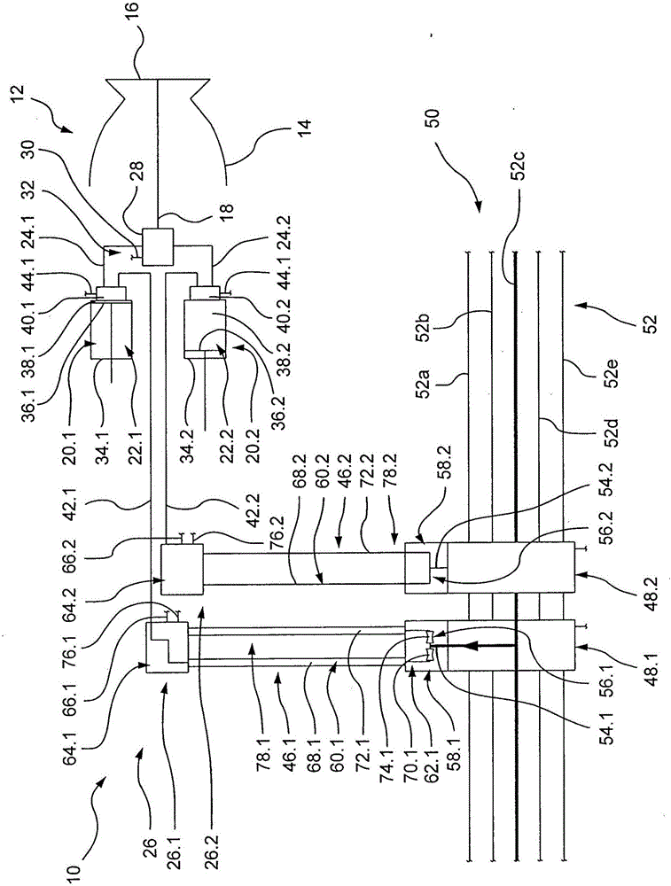
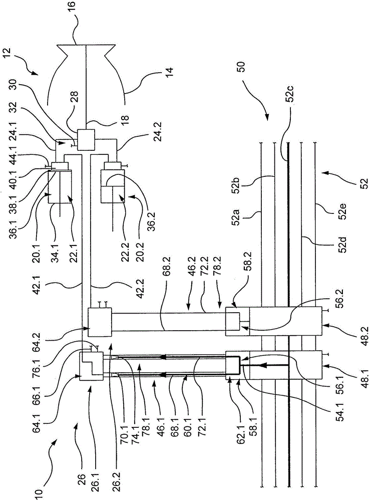
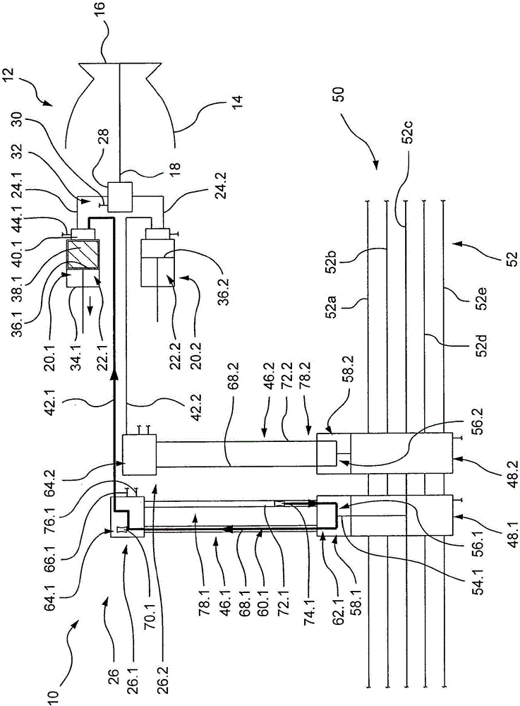
[0033] The drawing schematically shows a painting system 10 for painting objects such as vehicle bodies or parts or components thereof.

[0034] The painting system 10 includes a painting device 12 , which is only shown schematically in the present exemplary embodiment. In the present embodiment, the coating apparatus 12 is an electrostatically operated high speed rotary atomizer 14 having a rotating bell-shaped disk 16 .

[0035] The coating device 12 includes a discharge line 18 via which coating material can be discharged onto objects not specifically shown. In the present embodiment, the output conduit 18 leads to the bell disk 16 of the high speed rotary atomizer 14 . The bell-shaped disk 16 and the outlet duct 18 thus form an outlet device.

[0036] The coating device 12 may optionally be fed material from a first feed container 20.1 in the form of a first piston-type meter 22.1 through a first feed conduit 24.1 of a first supply line 26.1 or from a first feed containe...


PUM


Abstract

The invention relates to a coating system for coating objects, comprising an application device (12) and a supply system (26), by means of which the application device (12) can be supplied with a liquid material. The supply system comprises at least one base supply device (46.1) with a piggable supply line (60.1) which extends between a first pigging station (58.1) and a second pigging station (64.1) and can be connected to one of multiple material sources (52) by means of a supply unit (48.1). The piggable supply line (60.1) is a piggable primary supply line (68.1) which can be connected to a discharge line (54.1) of the supply unit (48.1) by means of a valve unit (56.1). A piggable secondary supply line (72.1) is provided which is connected to the valve unit (56.1) and is connected to a secondary pigging station (64.1; 80.1) at the end remote from the valve unit (56.1). The valve unit (56.1) is designed as a multi-way valve such that the discharge line (54.1) of the supply unit (48.1) can be at least selectively connected to the primary supply line (68.1); or the discharge line (54.1) of the supply unit (48.1) can be at least selectively connected to the primary supply line (68.1) and the secondary supply line (72.1); or the primary supply line (68.1) can be at least selectively connected to the secondary supply line (72.1).

Description

technical field [0001] The invention relates to a painting system for painting an object, the painting system comprising: [0002] a) coating equipment; [0003] b) a supply system by means of which liquid material can be delivered to the coating device; [0004] in, [0005] c) the supply system comprises at least one base-supply unit with a piggable / pig-cleanable supply pipeline extending between the first pig station and the second pig station and It is possible to connect to one of several material sources by means of the supply unit. Background technique [0006] Pipelines are currently understood to mean all flow paths for fluid media. This therefore includes, in addition to flexible hoses or rigid pipes, also channels, flow spaces or also only through-holes formed into the body. [0007] With such a painting system, for example in the automotive industry, objects such as vehicle bodies or body parts are painted by means of electrostatically operating coating devi...

Claims


Application Information

Patent Timeline
Patent Type & Authority Applications(China)
IPC IPC(8): B05B12/14B05B15/55
CPCB05B12/149B05B12/1481B05B15/55B05B5/1625B05B1/24B05B12/1472
Inventor F·克林克T·莫泽尔
Owner EISENMANN SE
Learn More