Low-carbon environmental protection charging circuit scheme

A charging circuit, low-carbon and environmentally friendly technology, applied in the electronic field, can solve problems such as complicated circuits and damage

Inactive Publication Date: 2017-03-01
CHONGQING NINGLAI SCI & TRADE
View PDF6 Cites 1 Cited by
  • Summary
  • Abstract
  • Description
  • Claims
  • Application Information

AI Technical Summary

Problems solved by technology

[0007] However, according to the above-mentioned charging method, the conventional circuit also has technical difficulties, because the conventional circuit is not a circuit that charges and discharges, and its switch control tube is the focus of the fault. If the switch tube is in a pulsed state, it will be easier. The probability of becoming damaged is one, and the second is because the circuit has the control of charging and the control of discharging part (or stop charging), so the damaged part has doubled, so if the traditional design is used, it must be The circuit is complicated, and new fault points have been added. How to solve these contradictions has become a new difficulty

Method used


Image

  • Low-carbon environmental protection charging circuit scheme
  • Low-carbon environmental protection charging circuit scheme
  • Low-carbon environmental protection charging circuit scheme

Examples


Embodiment Construction

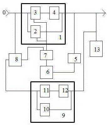
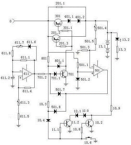
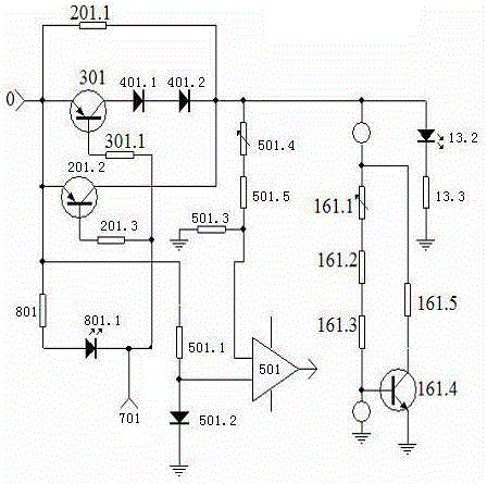
[0101] figure 1 , 2 , 3, 4, and 5 show an example of an implementation part, image 3 Figure 4 Figure 5 Example of detection map in implementation.

[0102] 1. Selection of components: IC 324 op amp, NPN triode 8050, PNP transistor 2N5401, diode surface-bonded diode, discharge resistor high-power type, and other resistance-capacitance components have no special requirements.

[0103] 2. Make the circuit control board, welding components: connect figure 2 Make the circuit control board according to the schematic diagram, connect figure 2 Schematic of soldered components.

[0104] 3. Power on, check and debug.

[0105] Check that the welding is correct, and then conduct power-on inspection and debugging.

[0106] 1. Check and debug the starting and ending unit (see image 3 ).

[0107] Connect a triode to form an adjustable voltage regulator analog circuit, instead of the charged battery as a dummy load. It is called dummy load later. Use the voltage file of the m...


PUM


Abstract

The invention relates to a low-carbon environmental protection charging circuit scheme, and belongs to an electronic technology. The low-carbon environmental protection charging circuit scheme is composed of a charging portion, a starting and ending unit, a pulse generating unit, an interface unit, a logic and charge display unit, a discharging portion and a load unit, and is characterized in that the charging portion and the discharging portion perform a scientific charging mode of charging while discharging on a charged battery when a power supply is turned on, the discharging portion is turned off when the charging portion is turned on, the discharging portion is turned on when the charging portion is turned off, a pulse charging mode in which the charging process is longer than the discharging process is formed, both the charging portion and the discharging portion are provided with a dormant circuit and an operating circuit, the dormant circuit is on standby when the operating circuit is in operation, and the dormant circuit is put into operation automatically when the operating circuit is damaged, so that utilization of a charger is guaranteed, the charging portion and the discharging portion are turned off when the charged battery is fully charged, and trickle current in the charging portion provides required maintenance trickle current for the charged battery, thereby realizing scientific pulse charging, and realizing environmental protection of the society.

Description

technical field [0001] It belongs to the technical field of electronic technology. Background technique [0002] Our company applied for a series of security products some time ago, and this product must have a backup battery, otherwise, when there is no mains power, the security function will become a fake, and when there is no mains power, it may be the peak of security accidents when. So a backup battery is required. And the performance of the backup battery is directly related to the overall performance. [0003] But the backup battery must be charged and maintained, and the scientific maintenance of the backup battery is directly related to the life and capacity of the backup battery. Some sources believe that batteries are often not worn out, but damaged due to improper charging. Batteries in security equipment are special-purpose batteries, which have special requirements for volume and capacity, and are more demanding than general products. Therefore, how to ens...

Claims


Application Information

Patent Timeline
Patent Type & Authority Applications(China)
IPC IPC(8): H02J7/00
Inventor 蒋凤
Owner CHONGQING NINGLAI SCI & TRADE
Why Eureka
Try Eureka