
Socket

A socket and plug technology, applied in the assembly/disassembly of base/housing, contact parts, contact parts, etc., can solve the problems of sealing, component cost increase, restriction and so on

Inactive Publication Date: 2017-03-01
SMK CO LTD
View PDF6 Cites 5 Cited by
  • Summary
  • Abstract
  • Description
  • Claims
  • Application Information

AI Technical Summary

Problems solved by technology

On the other hand, in the process of accommodating the inner housing 105 in the outer housing 101 on both surfaces of the socket 100, since the back side opening 102 of the outer housing 101 and a part of the bottom surface 101a are formed to avoid The slits such as the slots 114 that interfere with the leg portions 109b, 110b, 111b, 112b, and 113b of the spring terminals inserted into the housing 101 cannot be used for laser welding or ultrasonic welding to seal the contact surfaces. As a result, it is limited to waterproofing by attaching a waterproof adhesive to seal
[0019] However, the waterproofing treatment for attaching the waterproofing adhesive is performed by immersing the surface of the socket 100 subjected to the waterproofing treatment in the adhesive accumulation place where the waterproofing adhesive is accumulated, and therefore an additional step for the waterproofing treatment is required. work space, and part of the waterproof adhesive may flow into the plug accommodation chamber from the slits such as the above-mentioned slot 114, and adhere to the spring contact parts 109a, 110a, 111a, 112a, 113a to cause poor connection with the plug.
[0020] According to the existing socket 120, the feet of all the spring terminals 123 face the outside from the back side of the outer casing 121, so only the waterproof function on the back can be provided, but since the cover 124 is used to cover the supply The back side opening 122 through which the legs of many spring terminals 123 are inserted requires slits and recesses that do not interfere with the legs of the spring terminals 123 when the cover body 124 is assembled.
Therefore, these openings cannot be sealed by laser welding or ultrasonic welding. As a result, as described above, if the waterproofing treatment is performed to fill the sealing recess 125 with a waterproof adhesive, the waterproof adhesive may leak from the cover body 124. The slits and recesses penetrate into the outer casing 121
[0021] In addition, regardless of whether there is a waterproof function or not, the soldering positions of the spring terminals 123 and the conductive patterns of the printed circuit board are concentrated on the rear side of the socket 120, so the shape must be considered so that many spring terminals 123 and conductive patterns do not come into contact with each other. , configuration location, and wiring location have many constraints on the design
[0022] Furthermore, the leg of the spring terminal 123 whose spring contact portion is located on the front side must be drawn out to the back side opening 122, so the length along the insertion direction of the plug becomes longer, the spring terminal 123 formed of a metal material is enlarged, and the component cost is reduced. rise

Method used


Image

  • Socket
  • Socket
  • Socket

Examples


Embodiment Construction

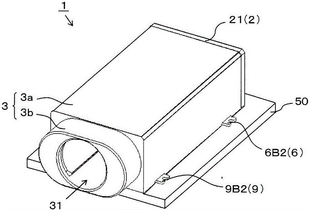
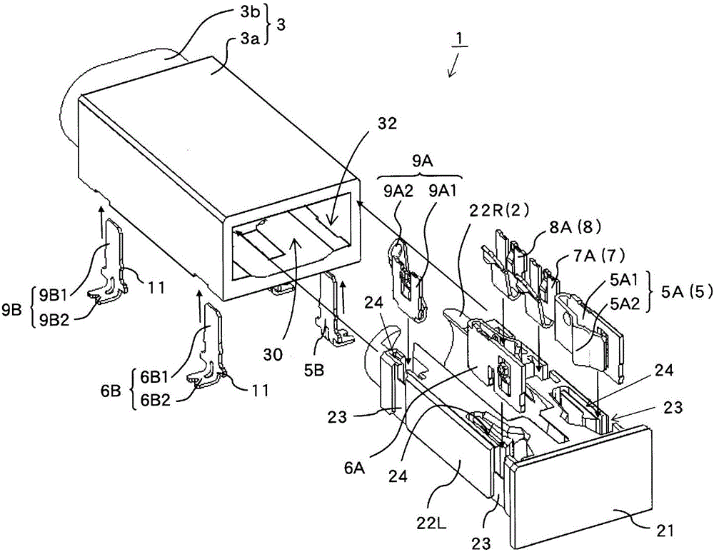
[0071] Below, use Figure 1 to Figure 8The socket 1 and its assembly method according to the first embodiment of the present invention will be described. It should be noted that, in this specification, the front side ( figure 1 The lower left side of the plug) is defined as the front, the back side along the insertion direction of the plug is defined as the rear, the bottom side facing the printed circuit board 50 is defined as the downward side, the upper side is defined as the upper side, and the direction of both sides is defined as Each part of the socket 1 will be described in the left-right direction.

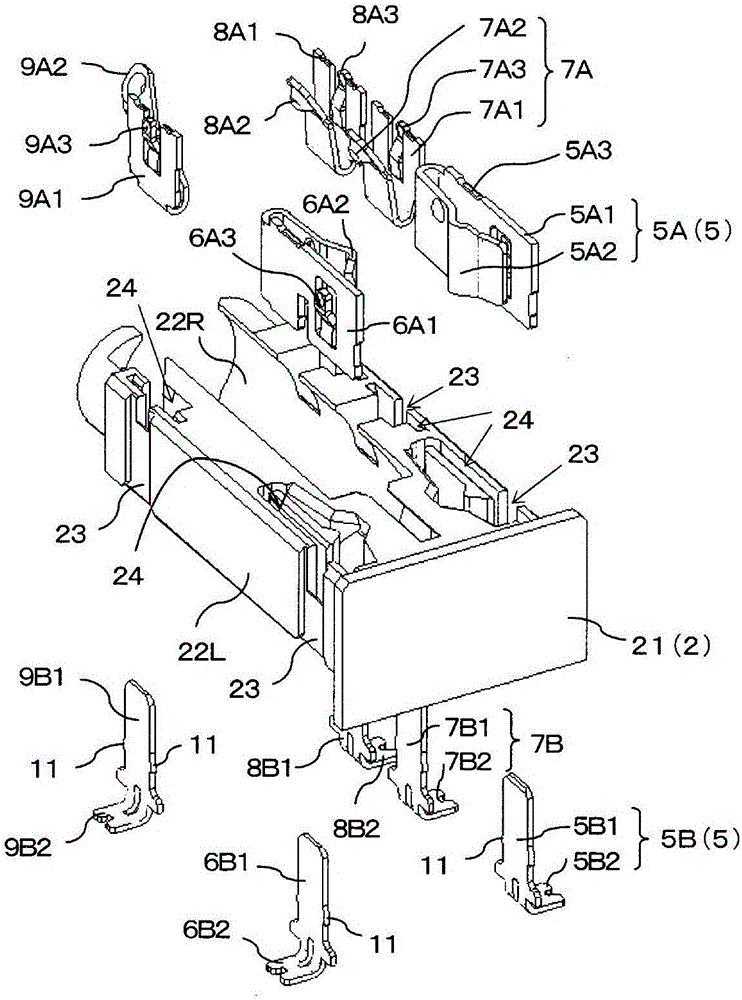
[0072] The socket 1 of the present embodiment is formed by injection molding of synthetic resin of insulating material and formed into a "U"-shaped inner shell 2; by injection molding of synthetic resin of insulating material and formed into a cylindrical outer shell 3; The first blade terminal 5, the second blade terminal 6, the first ring terminal 7, the second ring ...


PUM


Abstract

The invention provides a socket for sealing between a rear side opening portion of an outer housing and a lid body of an inner housing for covering rear side opening portion. A spring terminal is divided into a pair of spring piece portions attached to the inner housing and leg portions penetrating the outer housing and having tip end portions in contact with the spring piece portions which are inserted into the outer housing together with the inner housing. Since the leg portions are not attached into the inner housing inserted into the outer housing, it is unnecessary to form a clearance groove in the outer housing to avoid interference with the leg portions, and the rear side opening portion of the outer housing and the lid body of the inner housing for covering the rear side opening portion can be welded and sealed by laser transmission welding or ultrasonic welding.

Description

technical field [0001] The present invention relates to a socket which is mounted on a printed circuit board arranged in the case of various electronic equipment, is connected to a plug on the counterpart side, and outputs and inputs audio signals and video signals to and from the electronic equipment. Background technique [0002] In the past, the shell of the socket is constituted by two parts: an insulating outer shell and an inner shell housed in the outer shell, and the inner shell equipped with a plurality of spring terminals that are in contact with different contact positions of the plug is inserted into the outer shell. Assembled sockets are well known. [0003] Below, use Figure 10 , Figure 11 An example of this conventional outlet 100 will be described. 101 is an insulating outer casing, which is formed in a square tube shape as a whole, thereby forming a plug insertion chamber that communicates from the front plug insertion opening (not shown) at the upper le...

Claims


Application Information

Patent Timeline
IPC IPC(8): H01R12/71H01R13/02H01R13/502H01R13/52H01R43/20
CPCH01R12/71H01R13/02H01R13/502H01R13/52H01R43/20
Inventor 铃木洋
Owner SMK CO LTD
Learn More