
Laser cutting head with function of adjusting technological parameters in real-time mode

A technology of laser cutting head and process parameters, which is applied in laser welding equipment, manufacturing tools, metal processing equipment, etc., can solve the problems of high cost, high device cost, and adding beam switches, so as to achieve no need for lubrication and maintenance, avoid laser damage, The effect of low failure rate

Inactive Publication Date: 2017-03-01
SUZHOU LEAD LASER TECH
View PDF7 Cites 0 Cited by
  • Summary
  • Abstract
  • Description
  • Claims
  • Application Information

AI Technical Summary

Problems solved by technology

[0012] (1), complex structure, bulky, heavy weight,
[0013] (2) The number of lenses is large and generates a lot of heat, but limited by its movement needs, it cannot be directly cooled.
[0014] (3), the thermal lens effect limits the maximum power it can withstand,
[0015] (4) The movement of the lens may cause external particles to contaminate the interior of the cutting head,
[0016] (5) It takes a certain amount of time to move the lens, which is not suitable for fast and frequent parameter switching;
[0017] 2. Technical defects in the scheme of changing the focus diameter by switching the working optical fiber
The cost of this part of the device is also more expensive
And because the resonant cavity of the fiber laser and the working fiber are fused together, the cost of separate replacement is very high
Therefore, this technology cannot be used for lasers that have already been used in the factory
[0019] To sum up, the existing technical solutions for changing the focus diameter by switching the working optical fiber mainly have the following disadvantages: (1) the setting value cannot be continuously adjusted; (2) the manufacturing cost of the working optical fiber with double core Serious consequences; (3) Beam switch added

Method used


Image

  • Laser cutting head with function of adjusting technological parameters in real-time mode
  • Laser cutting head with function of adjusting technological parameters in real-time mode
  • Laser cutting head with function of adjusting technological parameters in real-time mode

Examples


Embodiment 1

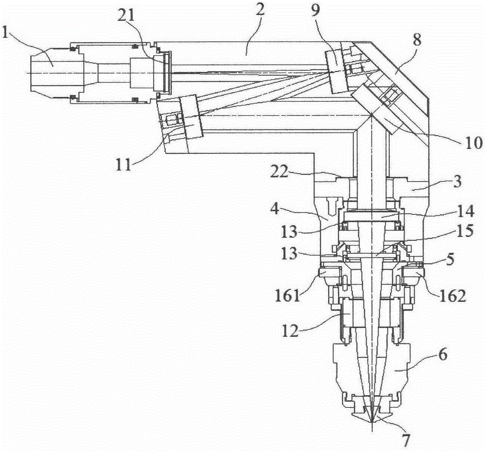
[0044] Embodiment 1: A laser cutting head with the function of adjusting process parameters in real time, including an optical fiber interface 1, a housing 2, an upper positioning ring 3, a connecting sleeve 4, a lower positioning ring 5, a capacitive sensor 6 and a nozzle 7, the housing The front end of the body 2 is provided with a front port 21, the end of the housing 2 is provided with an inclined mounting plate 8, and the lower end of the housing 2 is provided with a lower port 22;

[0045] The optical fiber interface 1 is installed to the front port 21 of the housing 2, and the inclined surface mounting plate 8 located at the end of the inner cavity of the housing 2 is sequentially installed with a variable curvature convex reflector 9 and a variable curvature reflector 10. A variable curvature concave reflector 11 is installed at the front end in the inner cavity of the body 2 and located below the front port 21. The light interface 1, the variable curvature convex refle...

Embodiment 2

[0052] Embodiment 2: A laser cutting head with the function of adjusting process parameters in real time, including an optical fiber interface 1, a housing 2, an upper positioning ring 3, a connecting sleeve 4, a lower positioning ring 5, a capacitive sensor 6 and a nozzle 7, the housing The front end of the body 2 is provided with a front port 21, the end of the housing 2 is provided with an inclined mounting plate 8, and the lower end of the housing 2 is provided with a lower port 22;

[0053] The optical fiber interface 1 is installed to the front port 21 of the housing 2, and the inclined surface mounting plate 8 located at the end of the inner cavity of the housing 2 is sequentially installed with a variable curvature convex reflector 9 and a variable curvature reflector 10. A variable curvature concave reflector 11 is installed at the front end in the inner cavity of the body 2 and located below the front port 21. The light interface 1, the variable curvature convex refle...


PUM


Abstract

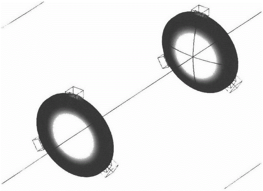
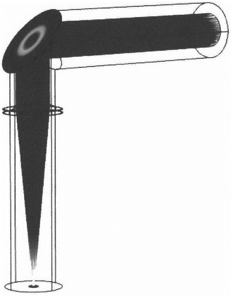
The invention discloses a laser cutting head with a function of adjusting technological parameters in a real-time mode. The head comprises a fiber interface, a housing, an upper positioning ring, a connecting sleeve, a lower positioning ring, a capacitive sensor and a nozzle. The front end of the housing is provided with a front port. The tail end of the housing is provided with a slope installing plate. The lower end located at the tail end of the housing is provided with a lower port. The fiber interface is installed at the front port of the housing. The slope installing plate located at the tail end of an inner cavity of the housing is sequentially provided with a curvature-changing convex-surface reflecting mirror and a curvature-changing reflective mirror from the top to the bottom. The position located at the front end of the inner cavity of the housing and located below the front port is provided with a curvature-changing concave-surface reflecting mirror. A light interface and the curvature-changing convex-surface reflecting mirror as well as the curvature-changing convex-surface reflecting mirror and the curvature-changing reflective mirror are respectively located on a first plane and a second plane located right under the first plane. The laser cutting head with the function of adjusting technological parameters in the real-time mode has following beneficial effects: sizes and positions of focal points can be independently set and changed at the same time without affecting each other; air pressure in the inner cavity of a cutting head does not change; and an optical assembly is long in service lifetime.

Description

technical field [0001] The invention relates to a laser cutting head with the function of adjusting process parameters in real time, and belongs to the technical field of laser cutting. Background technique [0002] As a fast and efficient processing method, laser cutting has been widely used in various industrial fields. But precisely because of its precise structure and high processing efficiency, it puts forward higher requirements for the operator. For example, regarding the mastery of the focus position, for raw materials of different materials and different thicknesses, a deviation of a few tenths of a millimeter in the focus position will lead to completely different processing effects. On the other hand, the size of the focal point also has a decisive impact on cutting. For example, when cutting thin plates, it is usually hoped that the focal point can be as small as possible, so that the energy of the laser can be highly concentrated in a small range, so that the o...

Claims


Application Information

Patent Timeline
IPC IPC(8): B23K26/38B23K26/064B23K26/70
CPCB23K26/38B23K26/0648
Inventor 扬·梅埃斯张鹏程
Owner SUZHOU LEAD LASER TECH
Learn More