Control device for electric-powered motor
A technology for control devices and motors, applied in the direction of electromechanical devices, circuit devices, circuit heating devices, etc., can solve the problems of increased power consumption, heat generation, and higher operating frequency, and achieve the effect of suppressing the influence of heat and electrical noise
- Summary
- Abstract
- Description
- Claims
- Application Information
AI Technical Summary
Problems solved by technology
Method used
Image

Examples
Embodiment approach 1
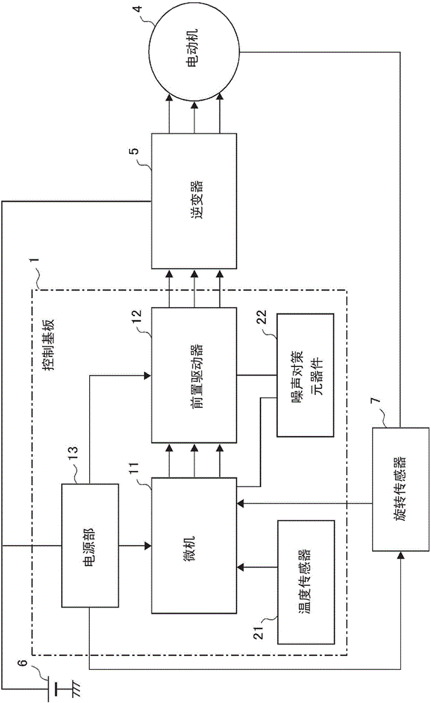
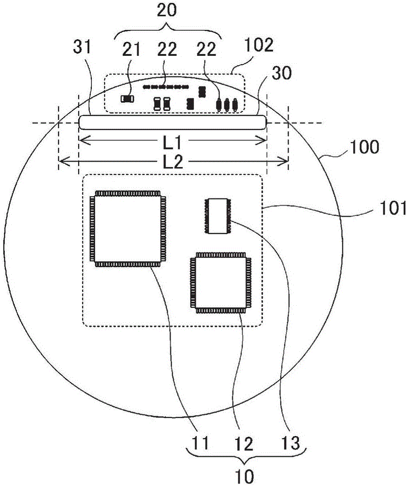
[0028] Hereinafter, the motor control device according to Embodiment 1 of the present invention will be described with reference to the drawings. figure 1 A configuration of a motor drive device including the motor control device according to Embodiment 1 is shown, figure 2 A control board of the motor control device according to the first embodiment is shown. In addition, the same code|symbol is attached|subjected to the same or a corresponding part in each drawing.
[0029] In the control board 1 of the motor control device ( figure 1 Indicated by a dotted line in ), a plurality of electronic components for controlling the driving of the motor, that is, the motor 4, are installed. The control board 1 performs control calculations for driving the motor 4 and drives the inverter 5 for driving the motor 4 . In addition, in Embodiment 1, a three-phase brushless motor is used as the motor 4 .
[0030] The microcomputer 11 performs control calculations for driving the motor 4...
Embodiment approach 2
[0066] Figure 5 ~ Figure 7 The separation tape of the control substrate according to Embodiment 2 of the present invention is shown. In this second embodiment, a case where the separation tape 30 includes a plurality of through holes 31 or notches 32 will be described as a modified example of the separation tape 30 described in the above-mentioned first embodiment. In addition, since the configuration of the motor drive device according to the second embodiment is the same as that of the above-mentioned first embodiment, the figure 1 Detailed description is omitted.
[0067] exist Figure 5 In the example shown, the separation belt 30 has three through-holes 31b, 31c, and 31d of the same shape, and these are arranged on a straight line. In addition, the number of through holes is not limited to three, and may be two or four or more. In addition, in Figure 5 Among them, although the three through-holes 31b, 31c, and 31d each have the same shape, they do not need to have ...
Embodiment approach 3
[0074] Figure 8 ~ Figure 9 The separation tape of the control substrate according to Embodiment 3 of the present invention is shown. In Embodiment 3, a case where a plurality of separation tapes 30 are provided on a substrate 100 will be described as a modified example of the separation tape 30 described in Embodiment 1 above. In addition, since the structure of the motor driving device according to the third embodiment is the same as that of the above-mentioned first embodiment, the figure 1 , omitting detailed description.
[0075] exist Figure 8 In the illustrated example, the separation band 30 composed of one elongated through-hole 31 is disposed at two upper and lower positions of the substrate 100 . In addition, in Figure 9 In the illustrated example, a separation band 30 including one elongated through hole 31 is disposed on the upper portion of the substrate 100 , and a separation band 30 having a notch 32 a and a through hole 31 d is disposed on the lower port...
PUM
 Abstract
Description
Claims
Application Information
 - R&D
- Intellectual Property
- Life Sciences
- Materials
- Tech Scout
- Unparalleled Data Quality
- Higher Quality Content
- 60% Fewer Hallucinations
Browse by: Latest US Patents, China's latest patents, Technical Efficacy Thesaurus, Application Domain, Technology Topic, Popular Technical Reports.
© 2025 PatSnap. All rights reserved.Legal|Privacy policy|Modern Slavery Act Transparency Statement|Sitemap|About US| Contact US: help@patsnap.com