
Metal shell manufacturing method and metal shell, electronic equipment

The technology of a metal shell and its manufacturing method, which is applied in the electronic field, can solve the problems of increasing the processing time of punching and forging shaving in CNC machining, increasing the difficulty of stamping and forming metal materials, etc.

Inactive Publication Date: 2017-02-22
BEIJING XIAOMI MOBILE SOFTWARE CO LTD
View PDF5 Cites 17 Cited by
  • Summary
  • Abstract
  • Description
  • Claims
  • Application Information

AI Technical Summary

Problems solved by technology

Due to the thicker thickness of the entire metal material, the shaving processing time of CNC machining punching and forging is increased, and the difficulty of stamping and forming of the metal material is increased.

Method used


Image

  • Metal shell manufacturing method and metal shell, electronic equipment
  • Metal shell manufacturing method and metal shell, electronic equipment
  • Metal shell manufacturing method and metal shell, electronic equipment

Examples


Embodiment Construction

[0045] Reference will now be made in detail to the exemplary embodiments, examples of which are illustrated in the accompanying drawings. When the following description refers to the accompanying drawings, the same numerals in different drawings refer to the same or similar elements unless otherwise indicated. The implementations described in the following exemplary examples do not represent all implementations consistent with the present invention. Rather, they are merely examples of apparatuses and methods consistent with aspects of the invention as recited in the appended claims.

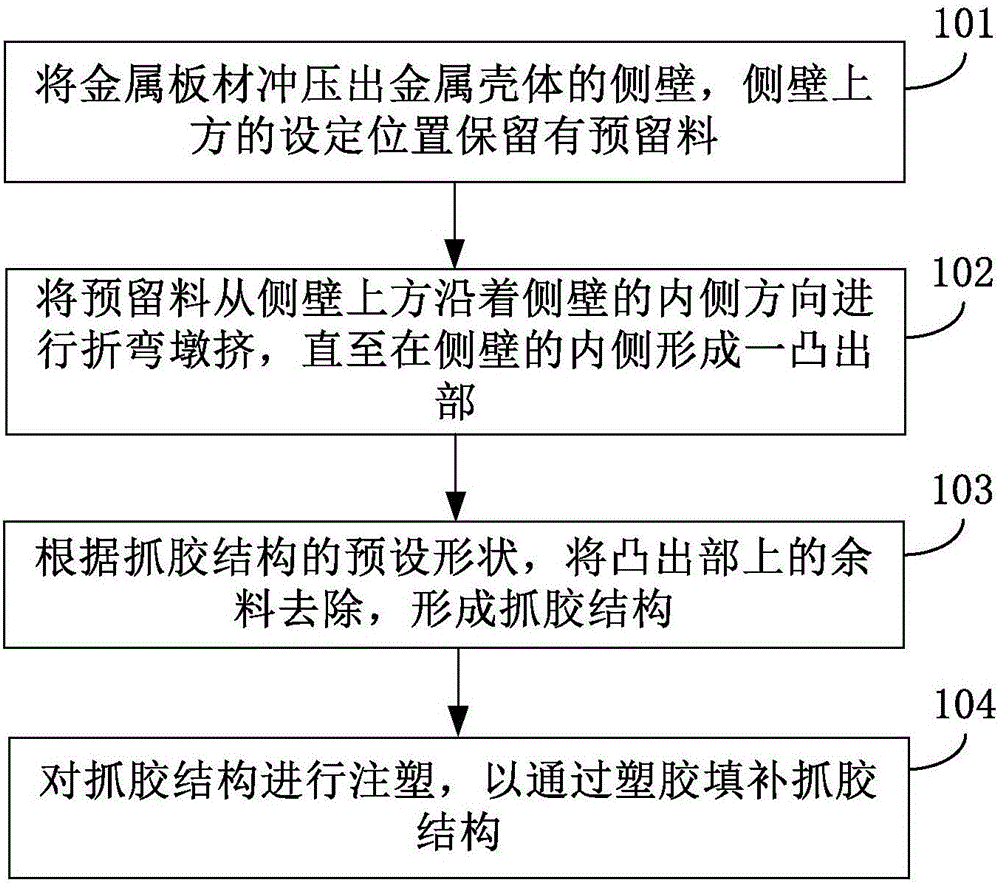
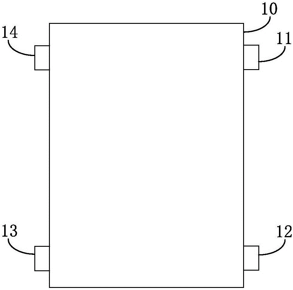
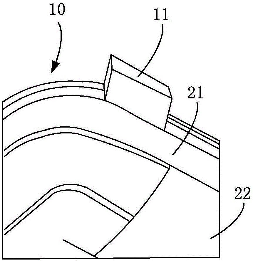
[0046] Figure 1A is a schematic flowchart of a method for manufacturing a metal shell according to an exemplary embodiment, Figure 1B yes Figure 1A A top view of the sheet metal used, Figure 1C yes Figure 1A A partial schematic diagram of the side wall of the metal casing punched through step 101 in the illustrated embodiment, Figure 1D yes Figure 1A In the shown embodiment, a schematic...


PUM


Abstract

The present disclosure relates to a method of manufacturing a metal shell and a metal case and an electronic device. Said method comprising: punching a sheet metal sheet into a side wall of a metal shell, said reservation position being retained above said side wall; placing said reservation material from said side wall above said side wall And a plurality of protrusions are formed on the inner side of the side wall; and the remaining material on the protruding portion is removed in accordance with a predetermined shape of the gripping structure to form the gripping structure And injecting the gripping structure to fill the gripping structure with plastic. The technical solution of the present invention can avoid the press molding of the metal sheet by CNC, reduce the difficulty of forming the metal material, save the time of processing the metal shell, and improve the production efficiency of the metal shell.

Description

technical field [0001] The present disclosure relates to the field of electronic technology, in particular to a method for manufacturing a metal casing, the metal casing, and electronic equipment. Background technique [0002] In order to satisfy the user's tactile and visual experience, more and more smartphones use metal shells. In related technologies, the unibody process is more about punching and forging a whole piece of metal material out of the basic shape of the metal shell, and then using a large number of computerized numerical control machine tools (Computerized Numerical Control Machine, referred to as CNC) to process The actual shape of the metal shell is stamped and forged. Since the metal shell needs to be fixed by the gripping structure after stamping, the thickness of the gripping structure determines the thickness of the required metal material, that is, the thickness of the metal material must be Only when the thickness of the gripping structure is greate...

Claims


Application Information

Patent Timeline
Patent Type & Authority Applications(China)
IPC IPC(8): G06F1/16H05K5/04
CPCG06F1/1626G06F1/1671G06F1/1684H05K5/04H04M1/0202B29L2031/3481B29C45/14221B29C45/14311B29K2705/00B21D22/02B23C3/12G06F1/1613
Inventor 冉剑波许多王有富
Owner BEIJING XIAOMI MOBILE SOFTWARE CO LTD
Learn More