Injection molding device for processing plastic protective cap and working method thereof

A technology for injection molding and protective caps, which is applied in the field of injection molding devices for processing plastic protective caps, can solve the problems of increasing the risk of molding, wasting production time, and reducing production efficiency, so as to improve the cleaning range, improve production efficiency, and save cost effect

Active Publication Date: 2020-11-13
宁国市锦鼎橡塑制品有限公司
View PDF4 Cites 0 Cited by
  • Summary
  • Abstract
  • Description
  • Claims
  • Application Information

AI Technical Summary

Problems solved by technology

[0003] At present, the cover-shaped mold can be made of two-plate mold or three-plate mold according to the requirements. When the glue inlet point is set on the top of the plastic part, a three-plate mold is generally used to facilitate glue feeding and demoulding, while the cover-shaped plastic part is in the molding process. It is easy to stick to the mold. Usually, the method of strengthening the ejection or adding a release agent is used. If the mold is glued, the pop-up mechanism will be added. However, since the pop-up mechanism is assembled on the mold core, if there is a problem with the pop-up mechanism during the actual production process , need to disassemble the mold for repair, the process wastes production time and reduces production efficiency; at the same time, it is very common for the material to fall off during production and cause the die to be molded, especially in the manual trial stage, the material is manually taken out, on the one hand, there is a safety hazard, on the other hand, it increases Compression mold risk, in reality, it is urgent to improve these problems

Method used


Image

  • Injection molding device for processing plastic protective cap and working method thereof
  • Injection molding device for processing plastic protective cap and working method thereof
  • Injection molding device for processing plastic protective cap and working method thereof

Examples


Embodiment Construction

[0023] The following will clearly and completely describe the technical solutions in the embodiments of the present invention with reference to the accompanying drawings in the embodiments of the present invention. Obviously, the described embodiments are only some, not all, embodiments of the present invention. Based on the embodiments of the present invention, all other embodiments obtained by persons of ordinary skill in the art without creative efforts fall within the protection scope of the present invention.

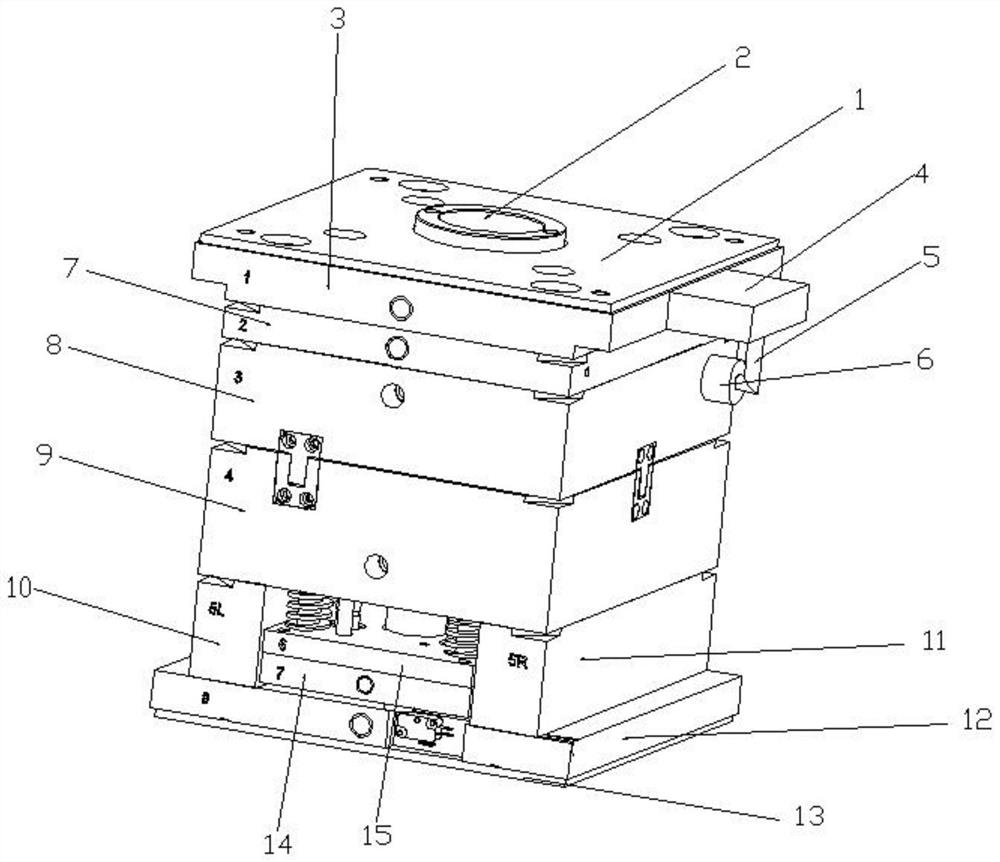
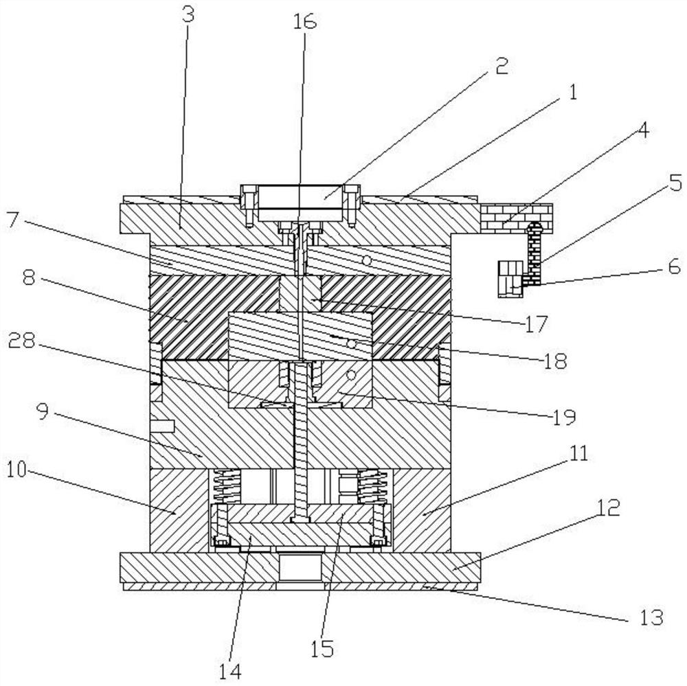
[0024] see Figure 1-5 As shown, an injection molding device for plastic protective cap processing includes an upper fixed template 3 and a lower fixed template 12, and the top of the upper fixed template 3 is fixedly connected with an upper heat insulation board 1 by screws for heat insulation. The right side of the upper fixed formwork 3 is fixedly connected with a support plate 4, and the bottom of the right side of the support plate 4 is rotatably connected wit...


PUM


Abstract

The invention discloses an injection molding device for processing a plastic protective cap and a working method thereof. A support plate is fixedly connected to the right side of an upper fixed template, one end of a support frame is rotatably connected to the bottom of the right side of the support plate, a powerful fan is fixedly connected to the other end of the support frame, a first mountinggroove matched with a sprue bushing is formed in the center of the top of the upper fixed template, the sprue bushing is fixedly mounted in the first mounting groove through screws, the upper fixed template is movably connected with a runner plate and a fixed template, the fixed template is positioned on the lower side of the runner plate, a fixed die core is fixedly mounted in the middle of thebottom end of the fixed template through screws, a runner block is movably mounted in the middle of the top end of the fixed template, and the runner block is extruded and fixed to the fixed templatethrough the top of the fixed die core. By the adoption of the structure, the plastic protective cap is easy to demold, unnecessary flash is prevented, a mechanism is convenient to disassemble, and repair and maintenance are facilitated.

Description

technical field [0001] The invention relates to the technical field of injection molding devices, in particular to an injection molding device for processing plastic protective caps and a working method thereof. Background technique [0002] Plastics are made by mixing synthetic resins with plasticizers, stabilizers, fillers and other substances, and the raw materials are in the form of small granules or powders. These small particles of plastic are heated and melted into a liquid, injected into a cavity with the desired product shape, and taken out after the plastic is cooled, a plastic part with the same shape as the cavity will be obtained. This thing with a cavity is a mold. The mold specially used to make plastic parts is called a plastic mold. [0003] At present, the cover-shaped mold can be made of two-plate mold or three-plate mold according to the requirements. When the glue inlet point is set on the top of the plastic part, a three-plate mold is generally used to...

Claims


Application Information

Patent Timeline
Patent Type & Authority Applications(China)
IPC IPC(8): B29C45/03B29C45/26B29C45/17B29C45/73B29C33/30B29C45/40
CPCB29C45/03B29C45/26B29C45/1753B29C45/73B29C33/30B29C45/4005
Inventor 叶建峰陈军合朱宗和葛浩
Owner 宁国市锦鼎橡塑制品有限公司
Why Eureka
Try Eureka