


Quick Research
Generate reliable direction feasibility study reports for your R&D in just a few steps.

Technical Q&A
Discover and master advanced knowledge NOW. Basics, ideas, possibilities, all at once.

Find Solutions
As an expert in R&D theories, this can generate solutions to your technical problems instantly.

Evaluate Feasibility
Analyze your overall solution with one click, know your potential R&D risks in advance.

Monitor Landscape
Get weekly tech updates, stay abreast of the latest tech innovations and key insights.
Optical unit and endoscope provided with optical unit
An optical unit and optical system technology, applied to endoscopes, optical elements, optics, etc., can solve problems such as optical performance degradation, misalignment of the lens frame and element frame, and inability to obtain optical performance, preventing optical performance. Deterioration of performance, effect of satisfying adequate quality
- Summary
- Abstract
- Description
- Claims
- Application Information
AI Technical Summary
Problems solved by technology
Method used
Image

Examples
no. 1 approach
[0041] First, an optical unit and an endoscope according to a first embodiment of the present invention will be described below with reference to the drawings.
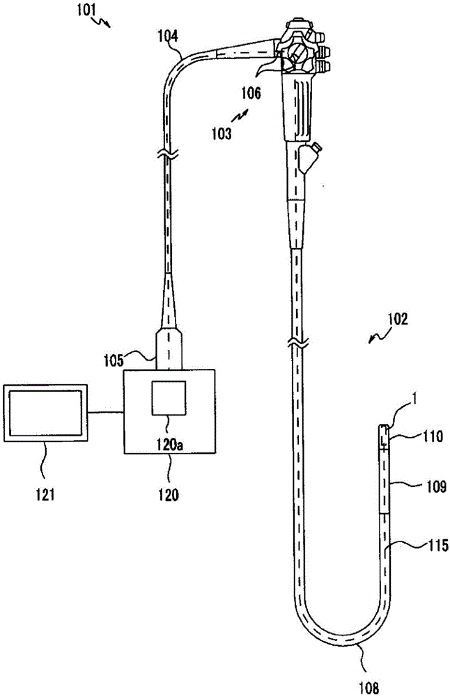
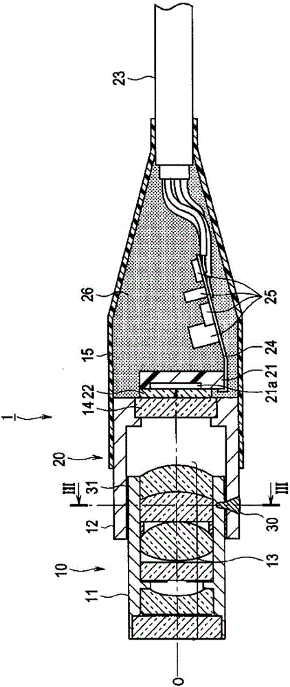
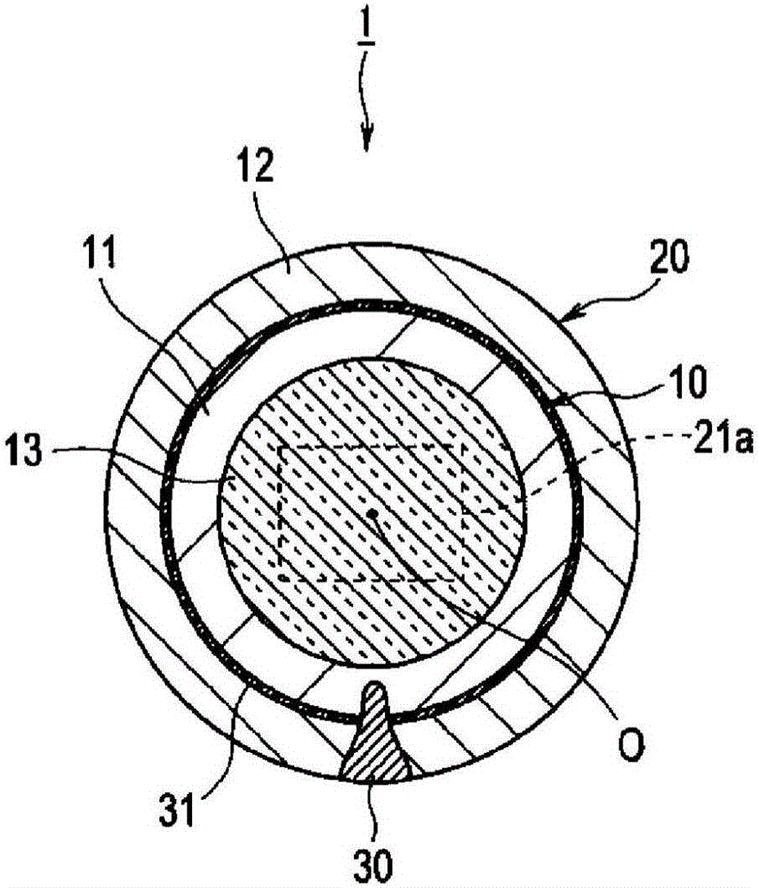
[0042] in addition, figure 1 is a diagram showing the structure of an endoscope, figure 2is a cross-sectional view showing the structure of the optical unit, image 3 is shown along figure 2 Cross-sectional view of the structure of the optical unit of the line III-III, Figure 4 It is a sectional view showing the state before the fitting of the lens unit and the imaging device unit, Figure 5 is a cross-sectional view showing a state in which the lens unit and the imaging device unit are fitted and fixed by a welding portion, Image 6 is a cross-sectional view showing a state in which the lens unit and the imaging element unit are fixed by a bonding material, Figure 7 is a cross-sectional view showing the structure of the optical unit of the first modified example, Figure 8 is a cross-sectional view illustra...
no. 1 example
[0112] like Figure 11 As shown, the imaging unit 1 may also adopt a structure in which a bonding material 31 for airtightly (watertightly) bonding the lens unit 10 and the imaging element unit 20 is applied to a part of the front end surface of the fitting portion of the imaging element holding frame 12 The edge (edge) is solidified.
no. 2 example
[0114] like Figure 12 As shown, the imaging unit 1 may also have a configuration in which a recessed peripheral groove 12 a functioning as a bonding material reservoir (adhesive reservoir) into which excess adhesive or the like flows is formed in the imaging element holding frame 12 . In the inner peripheral portion, the excess adhesive is the bonding material 31 for bonding the lens unit 10 and the imaging device unit 20 airtightly (watertightly).
[0115] In addition, in this reference example, the peripheral groove 12a is provided in the inner peripheral portion of the imaging element holding frame 12 on the proximal side of the fitting portion, but it is not limited to this, and may be formed in the fitting portion of the imaging element holding frame 12. the inner periphery of the department.
PUM
 Abstract
Description
Claims
Application Information
 - R&D Engineer
- R&D Manager
- IP Professional
- Industry Leading Data Capabilities
- Powerful AI technology
- Patent DNA Extraction
Browse by: Latest US Patents, China's latest patents, Technical Efficacy Thesaurus, Application Domain, Technology Topic, Popular Technical Reports.
© 2024 PatSnap. All rights reserved.Legal|Privacy policy|Modern Slavery Act Transparency Statement|Sitemap|About US| Contact US: help@patsnap.com