Prism unit and a projection image display apparatus
a projection image and display apparatus technology, applied in the field of prism units, can solve the problems of deterioration of optical performance and optical performance, and achieve the effects of reducing the use environment of the prism base, reducing the risk of optical performance deterioration, and high environmental reliability
- Summary
- Abstract
- Description
- Claims
- Application Information
AI Technical Summary
Benefits of technology
Problems solved by technology
Method used
Image
Examples
embodiment 1
[Embodiment 1]
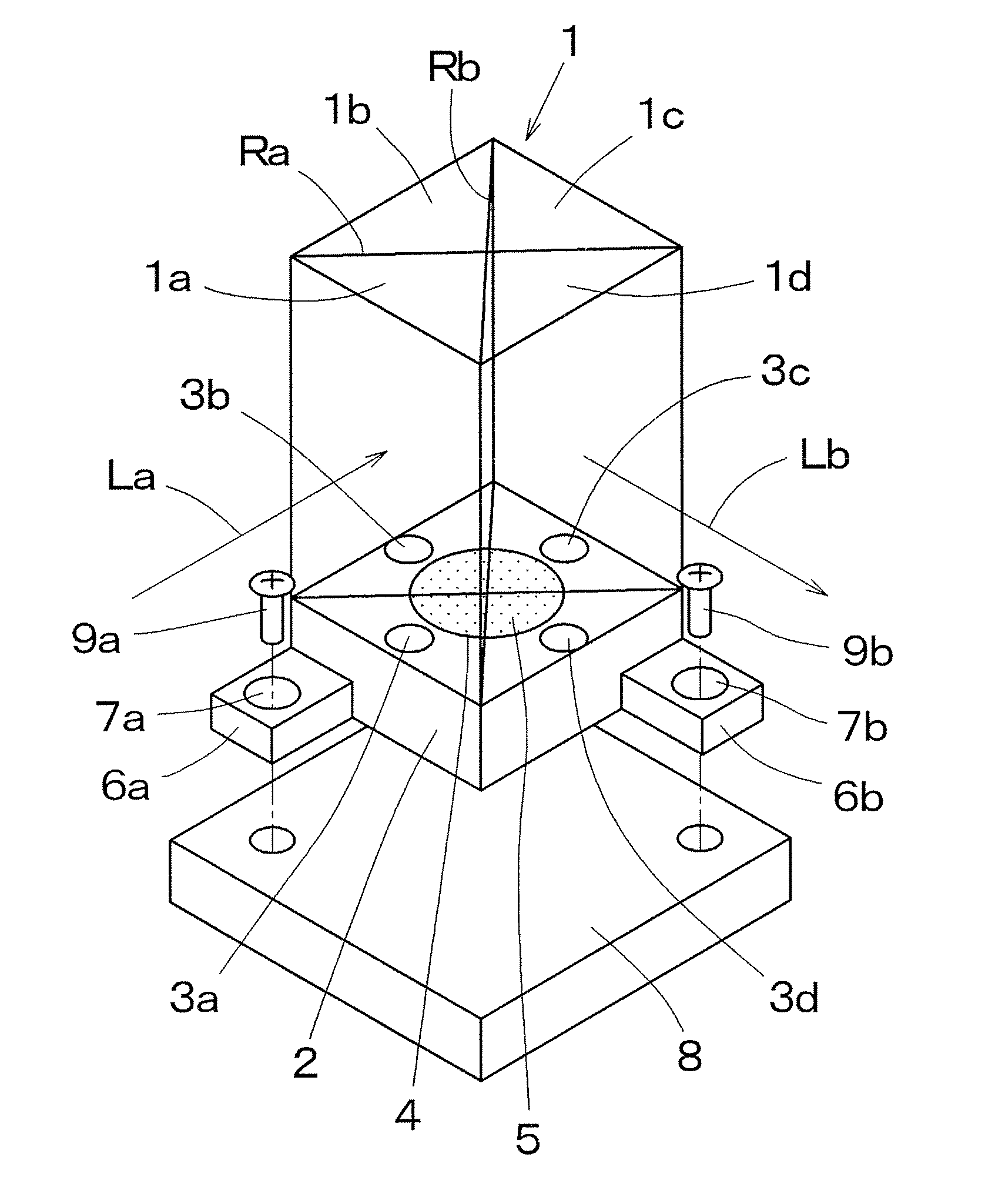
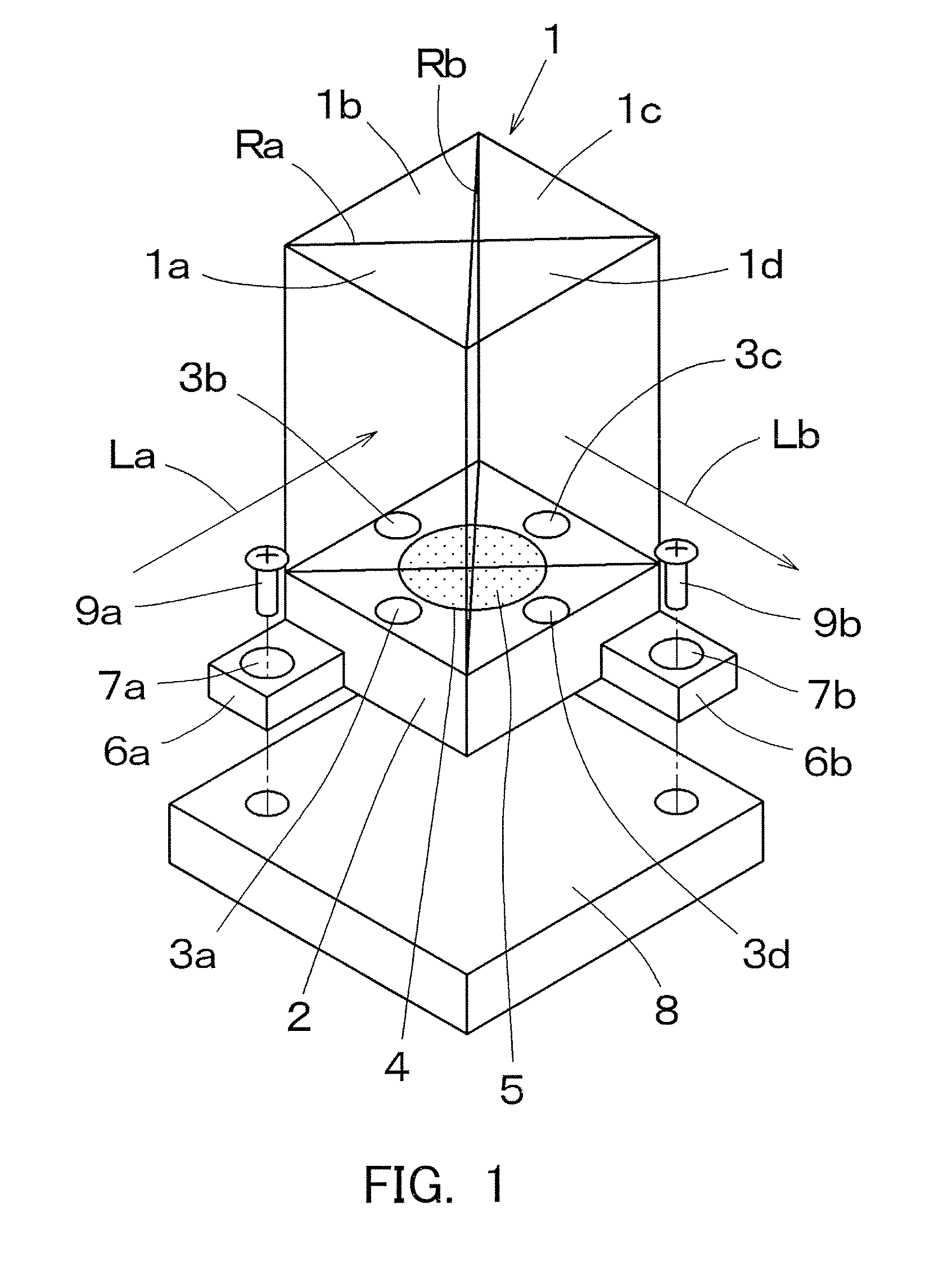
[0048]FIG. 1 is a perspective view of a prism unit which is formed by bonding a prism 1 to a prism base 2. Four rectangular-equilateral-triangle columnar prism members 1a are bonded to the prism 1, and the prism 1 has a square shape. At least three (or four in this embodiment) circular seating surfaces 3a to 3d that maintain parallelisms are disposed on the prism base 2. Two seating surfaces 3 are arranged on both sides of each of a reflecting surface (an optical surface) Ra that serves as a joining surface between prism members 1a and 1b and between prism members 1c and 1d and a reflecting surface (an optical surface) Rb that serves as a joining surface between 1a and 1d and between prism members 1b and 1c.
[0049]The prism 1 is positioned by bringing it into contact with the seating surfaces 3a to 3d, and has a seating surface bonded part 4 surrounded by the seating surfaces 3a to 3d, and formed on a surface of the prism base 2 located at a distant position; the prism...
embodiment 2
[Embodiment 2]
[0068]FIG. 8 is a perspective view of a prism unit according to a second embodiment. FIG. 9 is a plan view, FIG. 10 is a side view, and FIG. 11 is a sectional view of the prism unit. Three prisms 11, 12, and 13 are pasted onto one connection prism base 14. Three circular seating surfaces 15a to 15c are respectively disposed on the top surface of the connection prism base 14 to which the prisms 11 to 13 are joined, and the seating surfaces 15a to 15c are formed with defined parallelisms. Accordingly, the precision in the positional relationship between each other is ensured by placing the bottom surfaces of the prisms 11 to 13 on three seating surface 15a to 15c. Further, the seating surface bonded part 16 is disposed on the connection prism base 14 in a slightly lower position than the three seating surfaces 15a to 15c.
[0069]Although the above description has been given of the circular seating surfaces 15a to 15c and the circular seating surface bonded part 16, FIG. 1...
embodiment 3
[Embodiment 3]
[0070]FIG. 13 is a perspective view of a prism unit according to a third embodiment, which has a groove 21 configured to store extra adhesive 5 on the prism base 2 in addition to the structure of the prism unit in FIG. 1. Those reference numerals in FIG. 13, which are designated by the same reference numerals in FIG. 1, will be the same elements in FIG. 1.
[0071]In the arrangement of the seating surfaces 3 and the seating surface bonded part 4 according to the first embodiment, the adhesive 5 may stick out of the seating surface bonded part 4 in applying the adhesive 5 to the seating surface bonded part 4 that is slightly lower than the prism base 2 for the UV adhesion. Conceivably, the adhesive 5 which sticks out enters a small aperture between the seating surfaces 3a to 3d and the prism 1, and will bond them together.
[0072]In FIG. 13, the circular seating surface bonded parts 4 neighbor at four spots between the seating surfaces 3a to 3d and the seating surface bonded...
PUM
 Abstract
Description
Claims
Application Information
 - R&D
- Intellectual Property
- Life Sciences
- Materials
- Tech Scout
- Unparalleled Data Quality
- Higher Quality Content
- 60% Fewer Hallucinations
Browse by: Latest US Patents, China's latest patents, Technical Efficacy Thesaurus, Application Domain, Technology Topic, Popular Technical Reports.
© 2025 PatSnap. All rights reserved.Legal|Privacy policy|Modern Slavery Act Transparency Statement|Sitemap|About US| Contact US: help@patsnap.com


