
Distributed node seismometer network communication method

A distributed node and communication method technology, applied in the field of distributed node seismograph network communication, can solve problems such as difficulty in erection, high power of AP equipment, and inability of AP equipment to achieve full coverage of signals in the exploration area, and achieve good scalability and good The effect of robustness

Active Publication Date: 2017-02-22
JILIN UNIV
View PDF7 Cites 13 Cited by
  • Summary
  • Abstract
  • Description
  • Claims
  • Application Information

AI Technical Summary

Problems solved by technology

However, the power of AP equipment is high, and it is difficult to set up in the field, and AP equipment cannot yet achieve full coverage of signals in the exploration area
The introduction of wireless wide area network technology has realized the remote communication between the main control center and the collection station. However, the communication rate of the satellite network is limited, and the wide area network technology has obstacle blind spots in the complex terrain environment.
High real-time applications such as microseismic monitoring and hydraulic fracturing monitoring require on-site data recovery for the acquisition system, while wireless communication technology is mutually restricted in communication distance and link bandwidth, making it difficult for a single communication mode to solve large-scale mass data recovery. question
[0005] The inability of node seismic instruments to achieve on-site recovery of data in large-scale, high-density deep seismic exploration is the main reason restricting its development

Method used


Image

  • Distributed node seismometer network communication method
  • Distributed node seismometer network communication method
  • Distributed node seismometer network communication method

Examples


Embodiment Construction

[0045] In order to make the object, technical solution and advantages of the present invention more clear, the present invention will be further described in detail below in conjunction with the examples. It should be understood that the specific embodiments described here are only used to explain the present invention, not to limit the present invention.

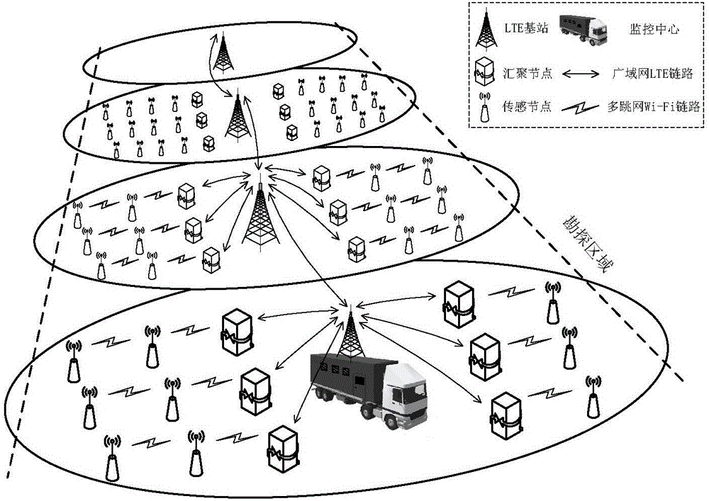
[0046] The distributed node seismograph communication method of the present invention is based on the three-dimensional seismic exploration topology: in the two-dimensional seismic exploration, the node seismographs are distributed in the exploration area in the form of survey lines; the three-dimensional seismic exploration is based on the two-dimensional construction arrangement Parallel deployment of multiple survey lines for acquisition has the characteristics of a static matrix topology. Both the sink node and the sensor node are node seismometers, and the data of each survey line is converged to the sink node, and the...


PUM


Abstract

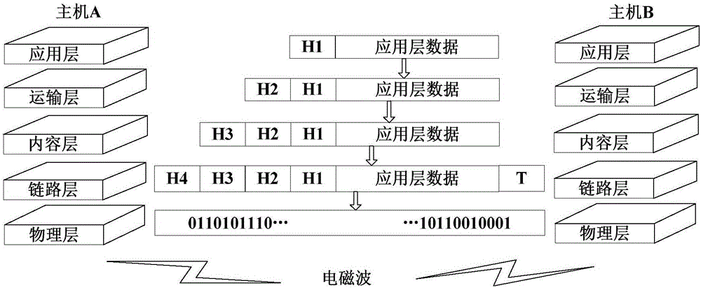
The invention relates to the network communication field, and especially relates to a distributed node seismometer network communication method. The method includes the following steps: a server is set as a monitoring center, wherein the monitoring center and sink nodes communicate through a wide area network, and multi-hop network communication is established between sense nodes and the sink nodes; in a network initial state, the monitoring center sets up the server and waits for network access applications of the sink nodes and the sense nodes, the sink nodes send the network access applications to the server by utilizing a TCP / IP through LTE links after being powered on, and connection between clients and the server is completed; and the sink nodes, as a gateway connecting the server with the sense nodes, communicate with the sense nodes by utilizing a private network protocol stack through Wi-Fi links. A layered architecture communication network of the wide area network and a multi-hop network is constructed, and a network routing protocol and a data transmission protocol are designed. A multi-hop data forwarding mode helps to overcome a contradiction between a short communication distance in terms of the wireless local area network technology and a low signal coverage rate under complicated geographic conditions in terms of the wireless wide area network technology.

Description

technical field [0001] The invention relates to the field of network communication, in particular to a method for network communication of a distributed node seismograph. Background technique [0002] Wired seismic exploration instruments have strong channel capability and high data quality assurance, occupying the vast majority of the seismic exploration instrument market. However, the construction cost of wired seismic equipment is high, and it cannot be applied to complex terrain such as mountains, ravines, rivers, and railways. Nodal seismographs do away with heavy cables and are not limited by terrain and track spacing, which is the long-term development trend of seismic exploration equipment. [0003] Communication technology is one of the key technologies in seismic exploration, which directly affects the scale and construction efficiency of the acquisition system. In the wired seismic instrument, the cable system is isolated from the outside world, so the wired sei...

Claims


Application Information

Patent Timeline
IPC IPC(8): H04W84/18G08C17/02
CPCG08C17/02H04W84/18
Inventor 林君宾康成张晓普佟训乾田入运高建
Owner JILIN UNIV
Learn More