Eureka AIR delivers breakthrough ideas for toughest innovation challenges, trusted by R&D personnel around the world.

Optical fiber transmitting and receiving device for communication network engineering

A fiber optic transceiver and communication network technology, applied in the field of fiber optic transceiver equipment, can solve problems such as button interference, internal circuit damage, and reduce the reliability of switches, so as to improve reliability and prevent damage

Inactive Publication Date: 2017-02-22
GUANGZHOU ZHONGTAN AIR PURIFICATION TECH CO LTD
View PDF6 Cites 0 Cited by
  • Summary
  • Abstract
  • Description
  • Claims
  • Application Information

AI Technical Summary

Problems solved by technology

[0003] As a kind of network equipment, fiber optic transceivers tend to accumulate heat inside after long-term operation. Therefore, the equipment is usually equipped with a heat dissipation mechanism to reduce the internal temperature. However, the existing heat dissipation mechanism has a fixed structure, which is not conducive to the installation of the heat dissipation mechanism. Disassembly and equipment maintenance. At the same time, the buttons on the fiber optic transceiver are not only susceptible to interference from external interference signals, but also lack the ability to absorb external peak voltages, causing damage to the internal circuit and reducing the reliability of the switch.

Method used


Image

  • Optical fiber transmitting and receiving device for communication network engineering
  • Optical fiber transmitting and receiving device for communication network engineering
  • Optical fiber transmitting and receiving device for communication network engineering

Examples


Embodiment Construction

[0026] The present invention is described in further detail now in conjunction with accompanying drawing. These drawings are all simplified schematic diagrams, which only illustrate the basic structure of the present invention in a schematic manner, so they only show the configurations related to the present invention.

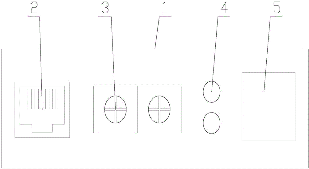
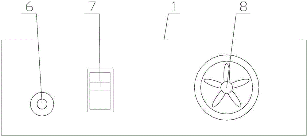
[0027] Such as Figure 1-Figure 7 As shown, a fiber optic transceiver device for communication network engineering, including a main body 1, the front of the main body 1 is provided with a network cable interface 2, a display screen 5, a number of binding posts 3 and a number of status indicator lights 4, the main body 1 There are data line interface 6, control button 7 and heat dissipation mechanism 8 on the back;

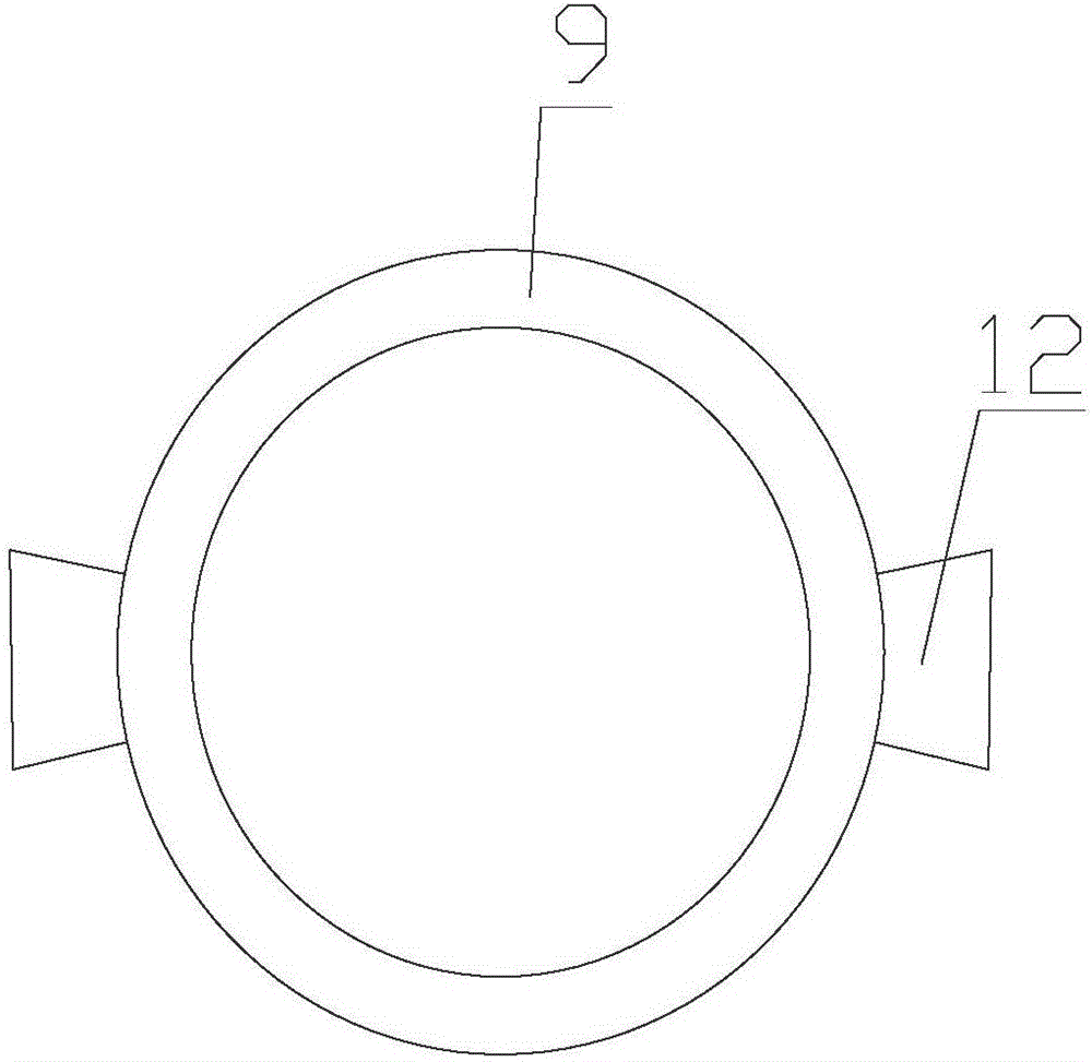
[0028] The heat dissipation mechanism 8 includes a mounting assembly 9 and a heat dissipation assembly. The mounting assembly includes a mounting plate 10, a return spring 11 arranged below the mounting plate 10 and a limiting assembly arranged o...


PUM


Abstract

The invention relates to an optical fiber transmitting and receiving device for communication network engineering. The optical fiber transmitting and receiving device comprises a main body. The front of the main body is provided with a network cable interface, a display screen, a plurality of terminal posts and a plurality of status indicator lights. The back of the main body is provided with a data line interface, a control key and a heat radiating mechanism. The optical fiber transmitting and receiving device for communication network engineering allows a mounting plate to be freely removed through cooperation between a rest spring and a limit spring, and is also capable of simple maintenance of the device through a mounting assembly in the heat radiating mechanism. In addition, in a control key circuit, a capacitor and a second resistor are used for respectively filtering interference signals and limiting the circuit, spike voltage is absorbed through a two-way voltage stabilizing diode, the internal circuit is prevented from being damaged, and thus the reliability of a switch is improved.

Description

technical field [0001] The invention relates to an optical fiber transceiver equipment used in communication network engineering. Background technique [0002] Optical fiber transceiver is an Ethernet transmission media conversion unit that interchanges short-distance twisted-pair electrical signals and long-distance optical signals. It is also called a photoelectric converter in many occasions. Products are generally used in actual network environments where Ethernet cables cannot be covered and optical fibers must be used to extend the transmission distance, and are usually positioned at the access layer of broadband metropolitan area networks, such as: high-definition video image transmission for monitoring security engineering, and at the same time It also plays a huge role in helping to connect the last mile of fiber to the metropolitan area network and beyond. [0003] As a kind of network equipment, fiber optic transceivers tend to accumulate heat inside after long-t...

Claims


Application Information

Patent Timeline
Patent Type & Authority Applications(China)
IPC IPC(8): H04B10/40H05K7/20
CPCH04B10/40H05K7/20
Inventor 蒙泽喜
Owner GUANGZHOU ZHONGTAN AIR PURIFICATION TECH CO LTD
Why Eureka
Eureka Blog
Learn More