
Device and method for reducing grounding resistance of grounding grid

A technology of impact grounding resistance and impact current, which is applied in the connection/disconnection direction of the connecting device, can solve the problems of obvious shielding effect and hinder the reduction of impact grounding resistance, so as to reduce the grounding network impact grounding resistance, easy breakdown, spark significant effect

Inactive Publication Date: 2017-02-22
DATONG POWER SUPPLY COMPANY OF STATE GRID SHANXI ELECTRIC POWER +1
View PDF6 Cites 9 Cited by
  • Summary
  • Abstract
  • Description
  • Claims
  • Application Information

AI Technical Summary

Problems solved by technology

As far as a single horizontal grounding body is concerned, increasing the number or length of buried grounding conductors can effectively reduce the power frequency grounding resistance, but when the length of the conductor increases to a certain value (this length is the effective length of the grounding body impact), with the length of the grounding body The power frequency grounding resistance continues to decrease, while the impact grounding resistance maintains a constant value and does not continue to decrease. The impact grounding resistance will also decrease with the increase of the length of the additional vertical grounding body, and finally tends to be stable. The additional vertical grounding body increases, and the impact grounding resistance decreases; but too many vertical grounding bodies, the shielding effect between the grounding bodies is obvious, which will hinder the reduction of the impact grounding resistance

Method used


Image

  • Device and method for reducing grounding resistance of grounding grid
  • Device and method for reducing grounding resistance of grounding grid
  • Device and method for reducing grounding resistance of grounding grid

Examples


Embodiment Construction

[0023] The present invention will be further described below in conjunction with the accompanying drawings and specific embodiments.

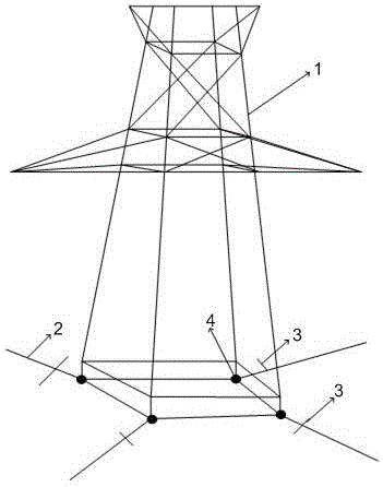
[0024] see Figure 1~5 As shown, the present invention provides a kind of device that reduces ground net impact grounding resistance, and it comprises at least one horizontal grounding conductor 2 that is fixed on the bottom of tower 1, and horizontal grounding conductor 2 is provided with at least one spark thorn conductor 3, and spark thorn conductor 3 is fixed between the middle of the horizontal grounding conductor 2 and the surge current injection point 4 of the horizontal grounding conductor 2 .

[0025] Specifically, by arranging the spark spur conductor 3 in the middle and front of the impulse current injection point 4 close to the horizontal ground conductor 3, a large part of the current at the injection point will be shunted to the spark spur conductor 3 during overcurrent, so that the spark spur The equivalent radius of the spark e...


PUM


Abstract

The invention discloses a device for reducing grounding resistance of grounding grid. The device comprises at least one horizontal grounding conductor which is fixed at the bottom of the tower. The horizontal grounding conductor is provided with at least one spark thorn conductor which is fixed between the middle part of the horizontal grounding conductor and the impingement current injection point of the horizontal grounding conductor. By setting the spark thron conductor at the front middle of the impingement current injection point near the horizontal grounding conductor, a large part of the current flow of the injection point will flow to the spark thorn conductor, so that the equivalent radius of the spark effect of the spark conductor is enlarged, the soil is more prone to breakdown, and the spark effect is very significant, which, at the same time, has a great influence on the current distribution of the horizontal grounding conductor, so that the resistance value of the grounding resistance is reduced, and the resistance reduction effect is remarkable.

Description

technical field [0001] The invention belongs to the technical field of lightning protection and grounding of electric power systems, and in particular relates to a device and method for reducing the impact grounding resistance of a ground grid. Background technique [0002] The grounding device of the transmission line is the basic guarantee and important measure to maintain the safe and reliable operation of the power system and to ensure the safety of electrical equipment and operating personnel. A grounding body with good impact characteristics can provide effective protection for transmission lines, thereby avoiding power outages caused by lightning strikes, which is of great significance to the safe operation of the power system and the reliability of power supply. [0003] With the development of my country's power grid and the improvement of power system stability, among all power system faults, the proportion of accidents caused by lightning strikes is on the rise. ...

Claims


Application Information

Patent Timeline
Patent Type & Authority Applications(China)
IPC IPC(8): H01R43/26
CPCH01R43/26
Inventor 赵培峰马征红袁勋张雷周玲陈青云
Owner DATONG POWER SUPPLY COMPANY OF STATE GRID SHANXI ELECTRIC POWER
Learn More