
Optical label shooting and optical label decoding relay work method

A working method and technology of optical tags, applied in the field of optical tags, can solve the problems of loss of use meaning of optical tags and loss of background information, so as to improve the on-site experience and ensure the effect of data transmission.

Active Publication Date: 2017-02-22
SHANGHAI OPTICS-VISION FUSION INTELLIGENT TECH CO LTD
View PDF5 Cites 6 Cited by
  • Summary
  • Abstract
  • Description
  • Claims
  • Application Information

AI Technical Summary

Problems solved by technology

If only the data information of the optical tag is collected, the background information it relies on will be lost; on the contrary, if only the background image information is collected, the optical tag will lose its use meaning

Method used


Image

  • Optical label shooting and optical label decoding relay work method
  • Optical label shooting and optical label decoding relay work method
  • Optical label shooting and optical label decoding relay work method

Examples


Embodiment 1

[0033] Example 1. Use iphone-6s plus for identification, background shooting and light tag decoding at the same time. First, at a certain time t, the shooting frequency of the camera is set to be (this series of parameters are called data acquisition state parameters):

[0034] Exposure time: 3×10 -5 Second;

[0035] ISO sensitivity: 664.7;

[0036] Shooting resolution: 4K (3840×2160);

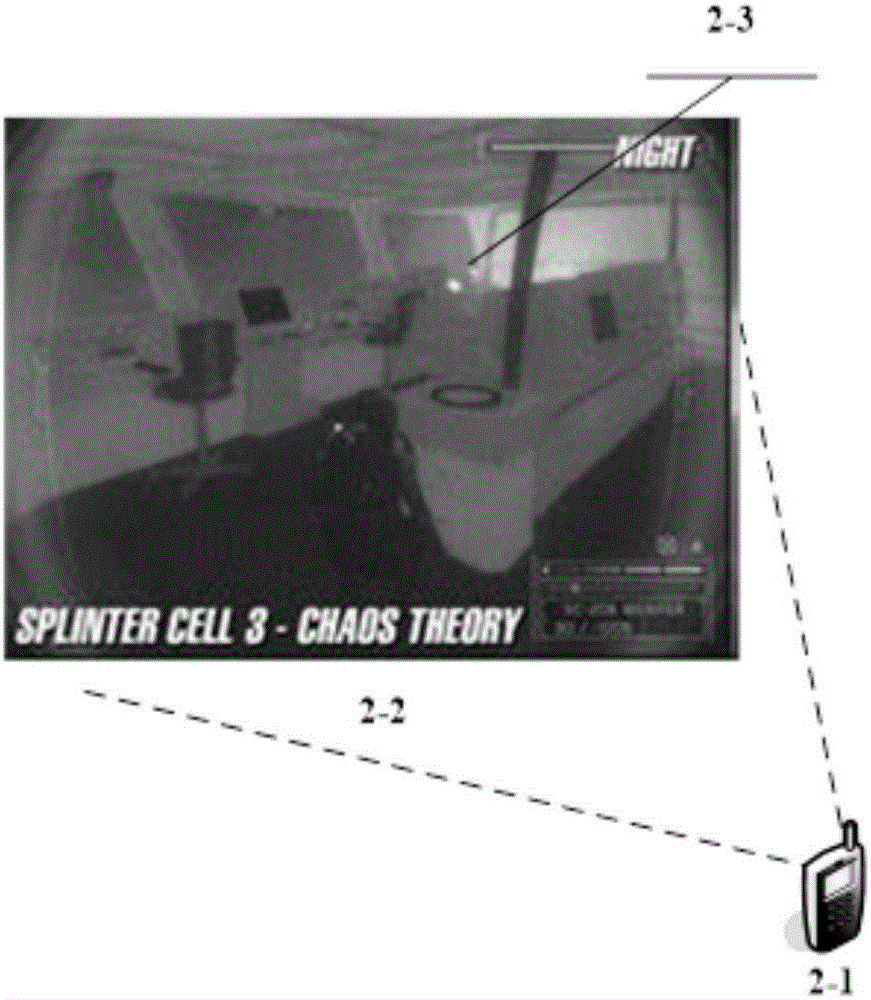
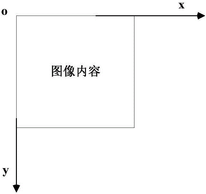
[0037] Carry out the positioning of the light tag in the scene, collect two adjacent frames of images and perform a difference to find the location identifier of the light tag, and then locate the position coordinates of the light tag in the image as (244,156); at t+1 second, then The shooting frequency of the camera is set as follows (exposure time and ISO sensitivity can be set automatically, or manually set appropriate values ​​according to the ambient light conditions. Here, the indoor environment is taken as an example, and this series of parameters are called shooting state parameter...


PUM


Abstract

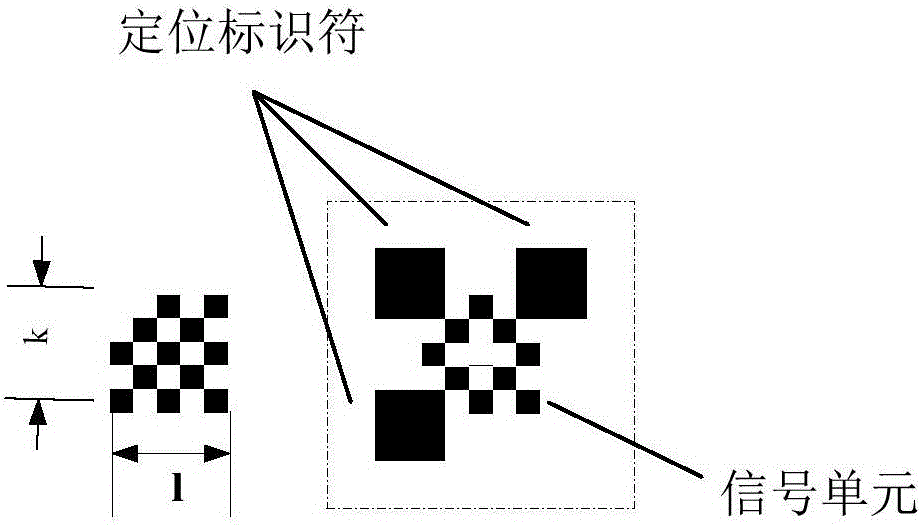
The invention provides an optical label shooting and optical label decoding relay work method. An optical label comprises two parts, i.e., a signal unit group or a "data bit" for short and a positioning identification or a "flag bit" for short. Through converting the shooting frequency of shooting equipment and eliminating a motion displacement image of the equipment, an optical label and a background image are simultaneously acquired, and alignment and superposing synthesis of two kinds of shooting image content are realized. Data transmission of the optical label is guaranteed, the background image where the optical label is disposed is also reserved, onsite experience of a user in using the optical label is improved, and the method solves the problems which cannot be solved by other label ( such as two-dimensional codes and bar-codes) methods.

Description

technical field [0001] The invention relates to an optical tag, in particular to an optical tag shooting and optical tag decoding relay working method. Background technique [0002] The optical label works at a high scanning frequency, while the background image around it needs to be collected at a relatively low scanning frequency. If only the data information of the optical tag is collected, the background information it relies on will be lost; on the contrary, if only the background image information is collected, the optical tag will lose its use meaning. Therefore, in order to take into account the collection of two kinds of image content, it is necessary to propose a reasonable working mode or method to collect them at the same time, and achieve the goal of least loss of information and no distortion. Contents of the invention [0003] The purpose of the present invention is to overcome the defects of the prior art, and provide a relay working method for optical lab...

Claims


Application Information

Patent Timeline
Patent Type & Authority Applications(China)
IPC IPC(8): G06K7/14
CPCG06K7/1443
Inventor 王晓东方俊李江亮苏爱民
Owner SHANGHAI OPTICS-VISION FUSION INTELLIGENT TECH CO LTD
Learn More