
Temperature field-thermal circuit direct coupling-based motor heat analysis method

An analysis method and temperature field technology, applied in the direction of electrical digital data processing, computer-aided design, special data processing applications, etc., can solve the problem of large-scale grid division, inability to simulate convective heat transfer of fully enclosed motors, and long calculation time And other issues

Active Publication Date: 2017-02-22
HANGZHOU EASITECH
View PDF6 Cites 13 Cited by
  • Summary
  • Abstract
  • Description
  • Claims
  • Application Information

AI Technical Summary

Problems solved by technology

Pure thermal path modeling can only represent the average temperature of each component, and there are errors when modeling components with complex geometric structures and uneven heat source distribution
However, the traditional finite element modeling method cannot simulate the convective heat transfer inside the fully enclosed motor, such as the convective heat transfer between the end winding and the casing and the convective heat transfer between the stator and the rotor. Large scale, long calculation time

Method used


Image

  • Temperature field-thermal circuit direct coupling-based motor heat analysis method
  • Temperature field-thermal circuit direct coupling-based motor heat analysis method
  • Temperature field-thermal circuit direct coupling-based motor heat analysis method

Examples


Embodiment Construction

[0051] The present invention will be further explained below in conjunction with the accompanying drawings.

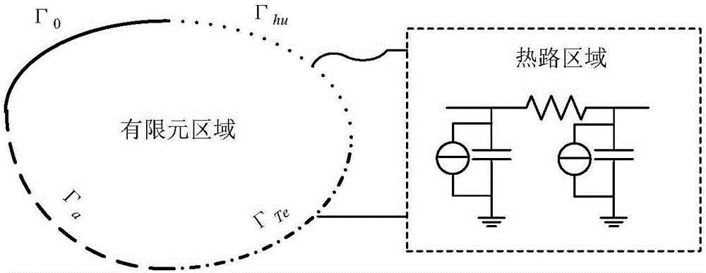
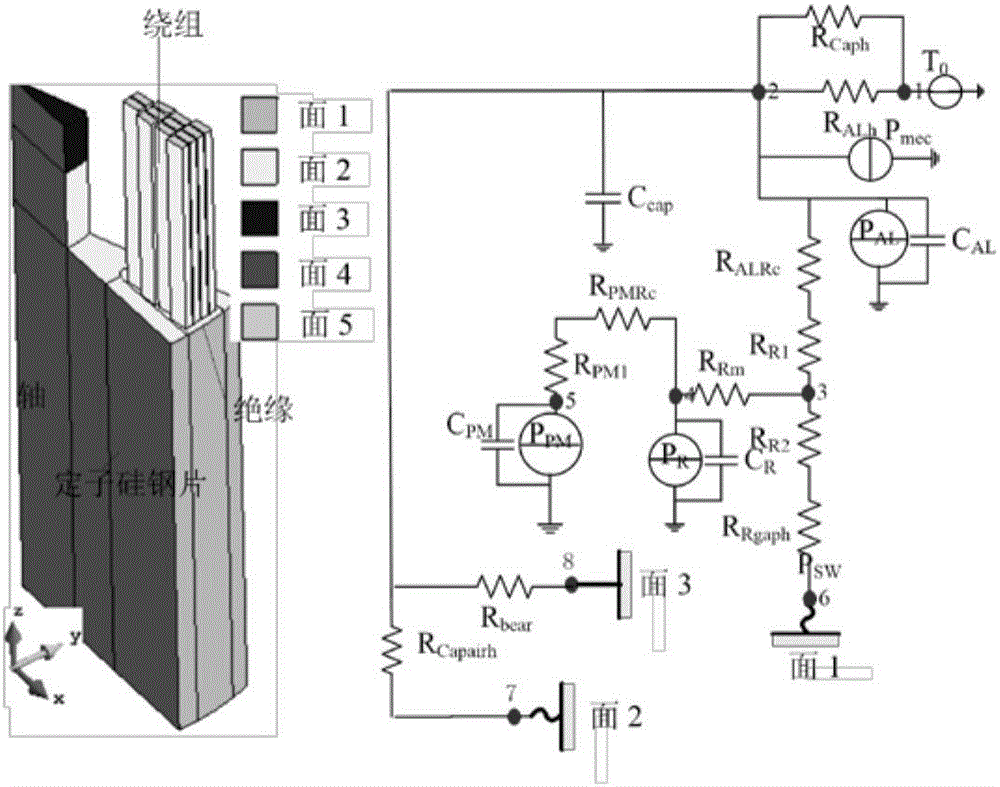
[0052] In this embodiment, a permanent magnet motor with an outer rotor structure is taken as an example to further describe the method. Considering the unevenly distributed winding AC copper losses, the inner stator part of the motor is modeled using the finite element method, while the outer rotor part is modeled using the thermal circuit method, as shown in the attached figure 2 shown. In the hot circuit area, node 1 represents the ambient temperature, node 2 represents the temperature of the end cover and aluminum shell, node 3 represents the middle temperature of the rotor silicon steel sheet, node 4 represents the average temperature of the rotor silicon steel sheet, node 5 represents the average temperature of the permanent magnet, and node 6 Represents the average temperature of the air gap, node 7 represents the average temperature of the air at the end, and...


PUM


Abstract

The invention discloses a temperature field and thermal circuit direct coupling-based motor heat analysis method. Part of parts of a motor are modeled by adopting a finite element method, and other parts are modeled by adopting a thermal circuit method. A temperature field is related to a thermal circuit through an equivalent temperature boundary and an equivalent convection boundary. During solving, a thermal circuit part is regarded to consist of one-dimensional finite element units, and two connected boundaries are regarded as two boundary units. Finally a unit stiffness matrix, a unit load matrix, a unit mass matrix and the like corresponding to the one-dimensional finite element units and the boundary units are superposed to a global stiffness matrix, a global load matrix and a global mass matrix, and the temperature field and the temperature distribution in the thermal circuit are worked out at the same time through a method for solving a global linear equation set. According to the method, the advantages of the finite element method and the thermal circuit method in the motor heat analysis are combined, so that sufficient calculation precision can be ensured and the calculation speed can be remarkably increased.

Description

technical field [0001] The invention relates to the field of finite element thermal analysis, in particular to a motor thermal analysis method directly coupled with a temperature field and a thermal circuit. Background technique [0002] With the intensification of the energy crisis, the society's demand for high-efficiency and low-cost motors continues to increase. Accurate motor design not only needs to calculate the electromagnetic performance of the motor, but also needs to accurately calculate the temperature rise of the motor during operation to ensure its safe operation. The traditional motor temperature rise calculation is mainly based on the thermal circuit method. This method usually only calculates the average temperature rise of the winding, and the establishment of the thermal circuit model and the calibration of parameters need to be combined with experiments. With the appearance of the finite element method and the rapid development of computer technology, ma...

Claims


Application Information

Patent Timeline
IPC IPC(8): G06F17/50
CPCG06F2119/08G06F30/23G06F30/367G06F30/17
Inventor 程明朱洒蔡秀花王景霞
Owner HANGZHOU EASITECH
Learn More