
Non-uniform velocity chirp scaling (CS) imaging method

An imaging method, high squint technology, applied in radio wave reflection/re-radiation, using re-radiation, measuring devices, etc., can solve problems such as inability to process echo signals, achieve high imaging resolution and low processing complexity , the effect of eliminating the influence

Active Publication Date: 2017-02-22
NORTHWESTERN POLYTECHNICAL UNIV
View PDF5 Cites 1 Cited by
  • Summary
  • Abstract
  • Description
  • Claims
  • Application Information

AI Technical Summary

Problems solved by technology

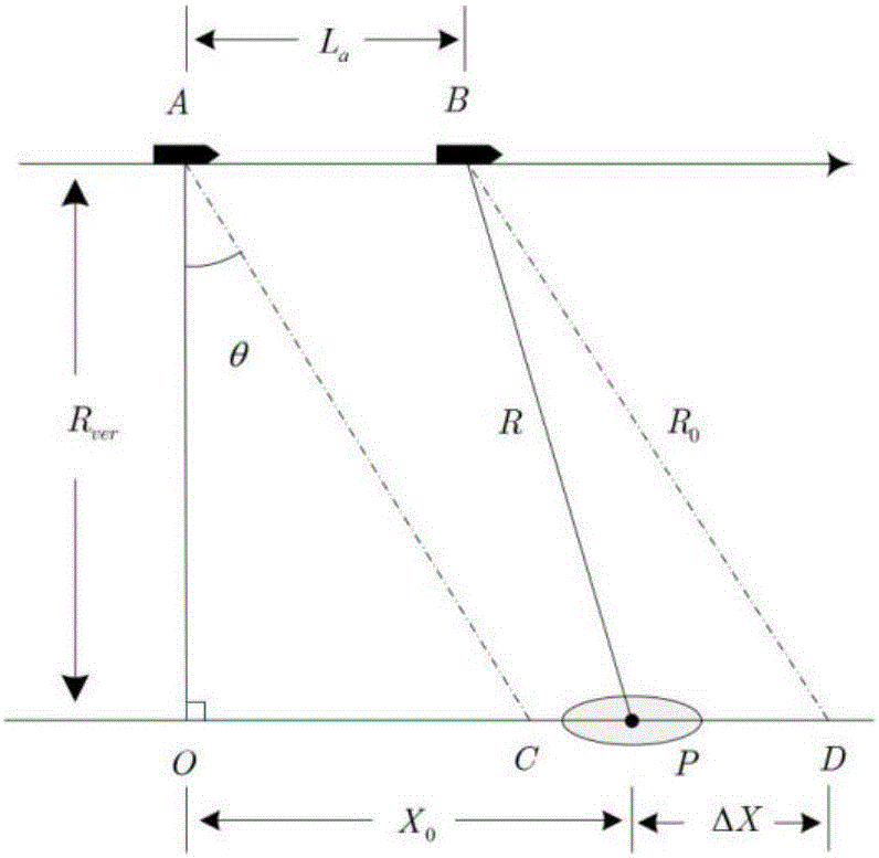
[0023] In order to overcome the distortion of the traditional time-domain correction distance walking CS imaging method under large oblique angle of view and the shortcomings of being unable to process the echo signal when the platform is not moving at a uniform speed

Method used


Image

  • Non-uniform velocity chirp scaling (CS) imaging method
  • Non-uniform velocity chirp scaling (CS) imaging method
  • Non-uniform velocity chirp scaling (CS) imaging method

Examples


Embodiment Construction

[0054] Now in conjunction with embodiment, accompanying drawing, the present invention will be further described:

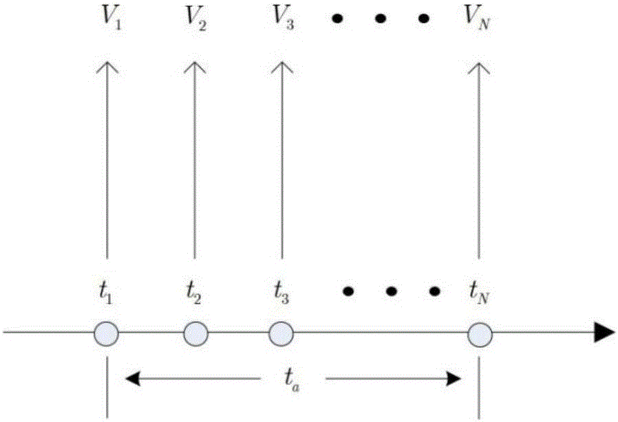
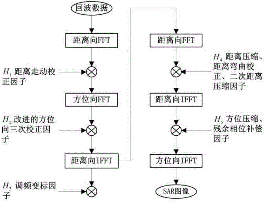
[0055] Step 1: Introduce the real-time sampling velocity generation sequence into the signal model and processing flow. Such as figure 2 As shown, if the radar is moving at a non-uniform speed, the instantaneous speed of each azimuth sampling point is not constant. Generate a velocity sequence from the instantaneous velocities of all azimuth sampling points within the length of a synthetic aperture, if the number of azimuth sampling points is N, then the velocity sequence V=[V 1 V 2 …V N ]. It replaces the velocity constant V in the signal model and all compensation and correction functions in the subsequent processing, that is, the introduction of the real-time sampling velocity sequence is completed.

[0056]Step 2: Perform range-wise FFT on the echo signal, and then multiply it by the walking correction function. The function expression is:

[0057] ...


PUM


Abstract

The present invention relates to a non-uniform velocity CS imaging method which eliminates the influence of the platform non-uniform velocity motion on an imaging result on the basis of a conventional time domain walk correction CS imaging method, and by analyzing a non-uniform velocity signal model and introducing a velocity sequence and a tertiary correction function. The non-uniform velocity CS imaging method of the present invention not only can obtain the higher imaging resolution, but also is lower in processing complexity by not having the interpolation operation, and is suitable for the synthetic aperture radar (SAR) imaging of various miniature platforms.

Description

technical field [0001] The invention belongs to the field of synthetic aperture radar (SAR) imaging, and in particular relates to a time domain walking correction Chirp Scaling (CS) imaging method under the condition of large squint under the condition of non-uniform velocity. Background technique [0002] Synthetic Aperture Radar (SAR) imaging has the advantages of long-distance, all-day, all-weather, and strong penetration. In particular, high-squint SAR imaging can flexibly change the beam direction and perform high-resolution imaging of the front area of ​​the battlefield. It enhances the ability to obtain battlefield information, and can provide terrain matching navigation and SAR image guidance for UAVs and cruise missiles, which has high application value. However, small platforms such as unmanned aerial vehicles and cruise missiles are small in size and are susceptible to changes in speed due to meteorological conditions, which makes the sampling of echo data uneven ...

Claims


Application Information

Patent Timeline
IPC IPC(8): G01S13/90
CPCG01S13/9017G01S13/9041G01S13/9011
Inventor 张研王保平李育朱孟元
Owner NORTHWESTERN POLYTECHNICAL UNIV
Learn More