Optical fine measurement method based on parallel imaging

A parallel imaging and optical technology, applied in the field of optical measurement, can solve the problems of uncertain millimeter-level deviation, increase hardware cost, impact, etc., and achieve the effect of contrast enhancement, increased precision and accuracy

Inactive Publication Date: 2017-02-22
XIJING UNIV
View PDF5 Cites 3 Cited by
  • Summary
  • Abstract
  • Description
  • Claims
  • Application Information

AI Technical Summary

Problems solved by technology

Although there are fixed tooling to determine the clamping position of the workpiece, due to the uncertain millimeter-level deviation every time, this deviation has a very large impact on the measurement requirements of the precision at the Miao level.
[0003] 2) The workpiece cannot be concentrated on the same plane due to its own contour or feature points, but it is necessary to extract all the contour curves or feature points with high precision at one time. Since the general optical system has a certain depth of field, the acquisition of images Sometimes the focus plane needs to be determined on a certain plane with a very short depth. Such a workpiece cannot meet the accuracy requirements of the test when it is measured in a spatial range. It often requires multiple stations to split the measurement task into different ranges, which increases the The cost of hardware is increased. Since each station needs to work together, it also has high requirements for software control and hardware installation accuracy, so the probability of success is very low.
[0004] 3) General non-contact measurement of workpieces has high requirements on the external lighting environment
If the perpendicularity cannot be guaranteed, there will be different degrees of shadows in the angular area of ​​the angle between the lens and the workpiece along the optical axis
If the user uses a black-and-white camera for size measurement, it is difficult to find the edge contour of the workpiece during the process of taking the grayscale image, so the measurement accuracy cannot be guaranteed

Method used


Image

  • Optical fine measurement method based on parallel imaging
  • Optical fine measurement method based on parallel imaging
  • Optical fine measurement method based on parallel imaging

Examples


Embodiment Construction

[0027] The present invention is further described below in conjunction with embodiment.

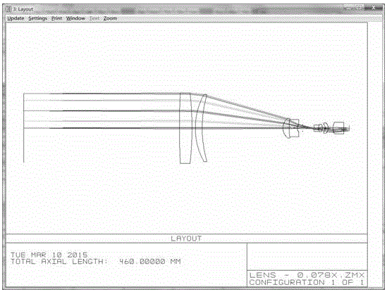
[0028] Such as figure 1 As shown, a method of optical fine measurement based on parallel imaging includes the following steps:

[0029] 1) The optical system of the whole lens is designed by combining the optical structure of the object-space telecentricity and the image-space telecentricity. The clear aperture of the diaphragm meets the telecentricity requirements of the entire optical system;

[0030] 2) Large depth of field with almost zero distortion:

[0031] The object telecentric structure can ensure that the lens has a larger depth of field when the object distance is fixed. Only the light rays parallel to the main optical axis on the object side of the lens are refracted by the optical system and then converged through the diaphragm. The object distance is guaranteed in the optical structure. The depth within the range of 160mm can be imaged and the distortion is less than 0.0...


PUM


Abstract

The invention relates to an optical fine measurement method based on parallel imaging. The optical fine measurement method comprises the steps: 1, using an optical structure being both telecentric in object space and telecentric in image space to design an optical system of a whole camera lens, wherein the telecentric in object space image surface and the telecentric in image space object surface coincide in the diaphragm position of the whole system, and the clear aperture of the diaphragm is controlled to meet the telecentricity requirement of the whole optical system; 2, enabling the large depth of field to be close to zero distortion; 3, guaranteeing the amplification factors in the depth of field range are identical; 4, using front parallel back lighting, wherein the imaging quality of the camera lens is optimized to the maximum degree, and the accuracy of the test data is guaranteed.

Description

technical field [0001] The invention belongs to the technical field of optical measurement, and in particular relates to a method for optical fine measurement based on parallel imaging. Background technique [0002] 1) The problem of accuracy deviation caused by each workpiece clamping deviation. Although there is a fixed tool to determine the clamping position of the workpiece, due to the uncertain millimeter-level deviation each time, this deviation has a very large impact on the measurement requirements for precision at the Mio level. [0003] 2) The workpiece cannot be concentrated on the same plane due to its own contour or feature points, but it is necessary to extract all the contour curves or feature points with high precision at one time. Since the general optical system has a certain depth of field, the acquisition of images Sometimes the focus plane needs to be determined on a certain plane with a very short depth. Such a workpiece cannot meet the accuracy requir...

Claims


Application Information

Patent Timeline
Patent Type & Authority Applications(China)
IPC IPC(8): G01B11/24G02B27/00
CPCG01B11/24G02B27/0012G02B27/0025G02B27/0075
Inventor 刘哲于涛黄世奇姜杰
Owner XIJING UNIV
Why Eureka
Try Eureka