Oily water vacuum separating device

A vacuum separation, sewage oil-water technology, applied in heating water/sewage treatment, adsorption water/sewage treatment, water/sewage multi-stage treatment, etc., can solve poor oil-water separation effect, poor separation effect, low treatment efficiency, etc. problems, to achieve the effect of improving utilization value, reducing occupied space, and high separation efficiency

Active Publication Date: 2017-02-22
SHANGHAI HONESS ENVIRONMENTAL TECH CORP
View PDF4 Cites 1 Cited by
  • Summary
  • Abstract
  • Description
  • Claims
  • Application Information

AI Technical Summary

Problems solved by technology

Therefore, ships and catering industries are equipped with sewage oil-water separation devices, but many problems are still exposed in the process of use: on the one hand, the sewage oil-water separation devices perform oil-water separation treatment on the sewage oil and water to be treated under normal pressure, and the separation effect is not good. On the other hand, when the sewage oil and water to be treated flow into the filter element, the flow direction is disordered, which is not conducive to the timely floating of the oil collected on the filter element; therefore, the separation effect of oil and water is not good, often requires multiple cycles of treatment, and the treatment efficiency is low

Method used


Image

  • Oily water vacuum separating device
  • Oily water vacuum separating device
  • Oily water vacuum separating device

Examples


Embodiment Construction

[0033] In order to clarify the technical scheme and technical purpose of the present invention, the present invention will be further introduced below in conjunction with the drawings and specific embodiments.

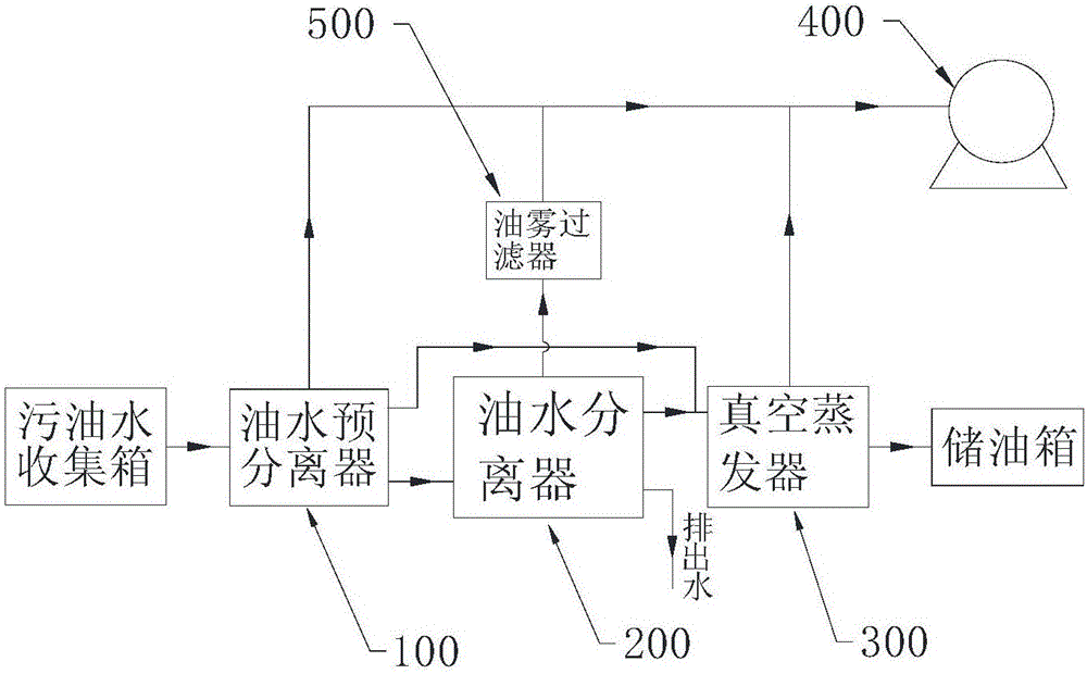
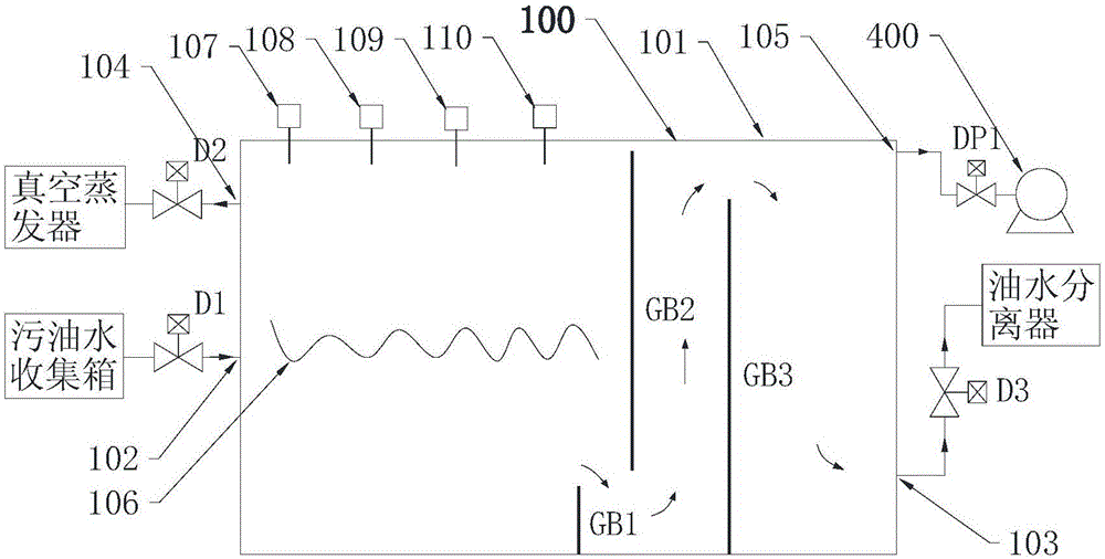
[0034] The vacuum separation equipment for dirty oil and water of the present invention, such as figure 1 As shown, the separation equipment includes an oil-water pre-separator 100, an oil-water separator 200, a vacuum evaporator 300, a vacuum pump 400, a diversion device 214, an oil storage tank, a dirty oil and water collection tank, and a controller. The controller is used to automatically control the separation equipment. The oil-water pre-separator 100 is used for pre-separating the oil and water to be treated. The oil-water pre-separator 100 is provided with a first suction port 105 for vacuuming, a first drain port 103 for draining slop oil, a first drain port 104 for draining slop oil, and a first drain port 104 for slop oil to be treated. The first input port 10...


PUM


Abstract

The invention discloses an oily water vacuum separating device which comprises an oil-water preseparator, an oil-water separator, a vacuum evaporator, a vacuum pump and a guiding device. A water draining port of the oil-water preseparator is communicated with an input port of the oil-water separator, an oil discharging port of the oil-water preseparator and an oil draining port of the oil-water separator are communicated with an input port of the vacuum evaporator, and an air exhausting port of the oil-water preseparator, an air exhausting port of the oil-water separator and an air exhausting port of the vacuum pump are communicated with the vacuum pump. A cylindrical filter element is built in the oil-water separator, and the guiding device comprises a guiding portion arranged in the same angle direction and is assembled inside the top of the filter element. The oily water vacuum separating device performs oil-water separation under vacuum conditions, the guiding device conducts flow guiding on oily water flowing towards the filter element and meanwhile conducts oil-water preseparation on oily water again, oily water drops gathered on the filter element are removed in time, the filtering load of the filter element is reduced, and improvement of the separation effect and the separation efficiency of the separating device is promoted.

Description

Technical field [0001] The invention relates to a sewage oil-water separation device, in particular to a sewage oil-water vacuum separation device that guides the flow direction of the sewage oil and water to be treated and performs oil-water separation under vacuum conditions, and belongs to the field of sewage treatment. Background technique [0002] With the rapid development of society and the substantial improvement of people's quality of life, people produce a large amount of oily sewage in daily life activities, such as domestic sewage generated in daily life activities, especially large amounts of catering sewage generated by the catering industry; The sewage produced by the ships that people travel and ride on contains a large amount of slop oil. The direct discharge of oily sewage will inevitably cause pollution to the river or the sea, and affect the normal growth of river organisms or marine organisms. The country and the International Maritime Organization have put ...

Claims


Application Information

Patent Timeline
Patent Type & Authority Applications(China)
IPC IPC(8): C02F9/10
CPCC02F1/001C02F1/04C02F1/28C02F1/40C02F9/00C02F2301/063C02F2301/08C02F2303/14
Inventor 陈鸽
Owner SHANGHAI HONESS ENVIRONMENTAL TECH CORP
Why Eureka
Try Eureka