Eureka AIR delivers breakthrough ideas for toughest innovation challenges, trusted by R&D personnel around the world.

Variable-rigidity flexible drive joint

A joint and stiffness technology, which is applied in the field of variable stiffness and compliant drive joints, can solve problems such as human safety threats, achieve the effects of reducing accidental injuries, improving contact safety, and expanding applications

Active Publication Date: 2017-02-22
CHINA UNIV OF PETROLEUM (EAST CHINA)
View PDF11 Cites 24 Cited by
  • Summary
  • Abstract
  • Description
  • Claims
  • Application Information

AI Technical Summary

Problems solved by technology

However, when people enter the task space of the robot and come into contact with it, the high stiffness will pose a threat to human safety

Method used


Image

  • Variable-rigidity flexible drive joint
  • Variable-rigidity flexible drive joint
  • Variable-rigidity flexible drive joint

Examples


Embodiment approach

[0030] Stiffness adjustment motor 27 drives planetary reducer 4 to rotate, planetary reducer 4 drives small spur gear 5 to rotate synchronously through shaft hole, small spur gear 5 meshes with large spur gear 6, and large spur gear 6 is fixed to drive disc 7 by screws 8 , and rotate on the fixed shaft 25 through the bearing 33, wherein the fixed shaft 25 is fixed on the motor casing 2 by the screw 26. The outer ring of the drive disc 7 cooperates with the inner ring of the joint housing 3 through the bearing 19 . Have 4 chutes on the driving disc 7, and the profile curve of the chutes is a constant speed helix.

[0031] The rotation of the chute will drive the movement of the slider 21 through the bearing 22, the slider 21 is fixedly connected with the ball spline sleeve 12, the ball spline sleeve 12 is connected with the ball spline 13 through the screw 14, and the whole can be moved along the spline shaft 11. Linear sliding, one end of the spline shaft 11 is connected with...


PUM


Abstract

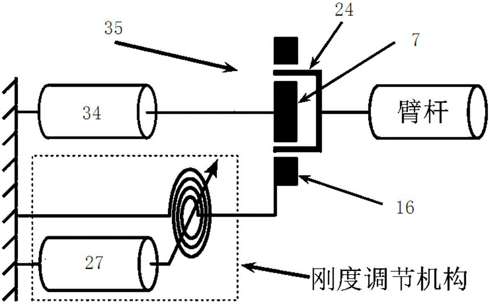
The invention discloses a variable-rigidity flexible drive joint. The variable-rigidity flexible drive joint comprises a joint shell, a joint motor and a harmonic reducer. The end portion of a motor shaft of the joint motor is connected with a wave generator of the harmonic reducer to serve as the input of the joint. The motor shaft is provided with a rigidity adjusting mechanism. A steel wheel of the harmonic reducer is fixed to one flange. The outer ring of the flange is matched with the joint shell through a bearing. A groove is formed in the flange and is in contact with one end of an elastic part. The other end of the elastic part is fixed. The deformable length of the elastic part is adjusted through the rigidity adjusting mechanism, and therefore flexible connection between the steel wheel and the joint is achieved, and a flexible wheel of the harmonic reducer serves as the output of the joint.

Description

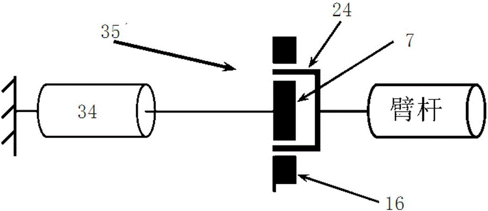
technical field [0001] The invention discloses a drive joint, in particular to a flexible drive joint with variable stiffness. Background technique [0002] Safety is the primary consideration in future robot development. The future development trend of robots should be to share the same living space with humans and work together. At present, the robot mainly adopts the way of rigid drive, such as figure 1 . The joint motor 34 is rigidly coupled with the arm rod to increase the rigidity of the system as much as possible to obtain accurate and fast response. However, when people enter the task space of the robot and come into contact with it, the high stiffness will pose a threat to human safety. Contents of the invention [0003] The invention discloses a compliant robot joint with variable joint stiffness. The joint is driven by two motors, the motor with larger torque is used as the driving motor of the joint; the motor with smaller torque is used to change the stiff...

Claims


Application Information

Patent Timeline
Patent Type & Authority Applications(China)
IPC IPC(8): B25J17/00B25J17/02
CPCB25J17/00B25J17/0208
Inventor 王新庆高娟刘艳立罗琳飞
Owner CHINA UNIV OF PETROLEUM (EAST CHINA)
Why Eureka
Eureka Blog
Learn More