Eureka AIR delivers breakthrough ideas for toughest innovation challenges, trusted by R&D personnel around the world.

Grinding technology and device for wheel groove finishing broach with equal cutting angles

A technology of wheel groove broach and fine broach, which is applied in the field of grinding technology of wheel groove broach, which can solve the problems of short service life, affecting the service life of wheel groove broach, and inconsistent broaching amount, so as to reduce the cutting force , Conducive to the effect of chip curling and low error value

Inactive Publication Date: 2017-02-22
EST TOOLS
View PDF9 Cites 6 Cited by
  • Summary
  • Abstract
  • Description
  • Claims
  • Application Information

AI Technical Summary

Problems solved by technology

The tooth-shaped working surface and non-working surface of the fir tree-shaped wheel groove broach ground in this way will form a single tooth and one side force due to the inconsistent broaching amount, which will affect the service life of the wheel groove broach
[0004] Therefore, the current grinding process of the fir tree-shaped wheel groove broach has the problem that the broaching amount of the tooth-shaped working surface and the non-working surface are inconsistent, and the single tooth of the broach after grinding is stressed on one side, and the service life is shorter.

Method used


Image

  • Grinding technology and device for wheel groove finishing broach with equal cutting angles
  • Grinding technology and device for wheel groove finishing broach with equal cutting angles
  • Grinding technology and device for wheel groove finishing broach with equal cutting angles

Examples


Embodiment Construction

[0035] The present invention will be further described below in conjunction with the accompanying drawings and embodiments, but not as a basis for limiting the present invention.

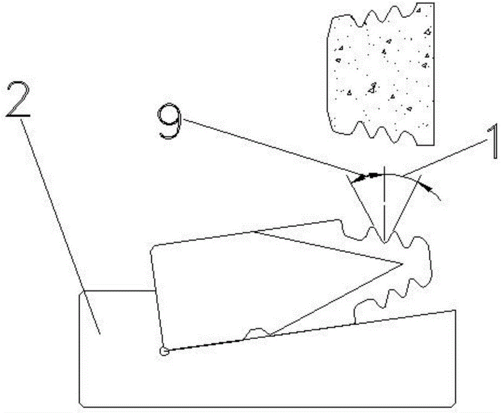
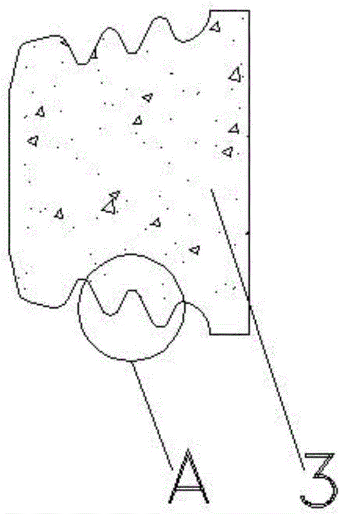
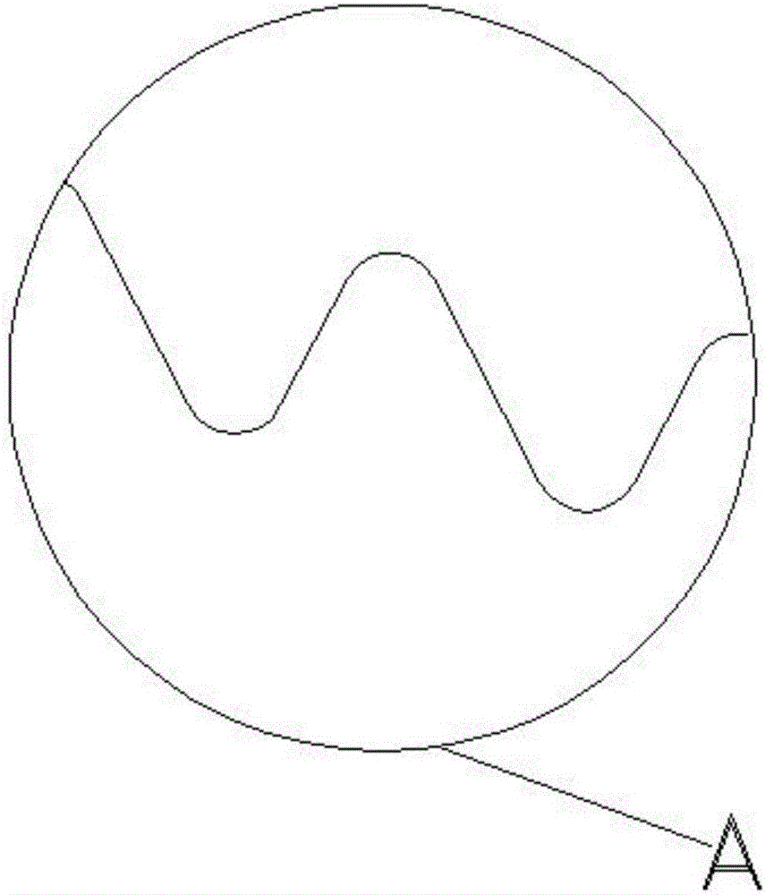
[0036] Example. A wheel groove fine broach grinding process with equal cutting angle, which is composed of figure 1 , figure 2 , image 3 , Figure 4 , Figure 5 , Figure 6 , Figure 7 , Figure 8 and Figure 9 shown, including the following steps,

[0037] a. Based on the fact that the tooth profile angle 1 of the working surface of the fir tree tooth profile of the wheel groove broach is equal to the tooth profile angle 9 of the non-working surface of the fir tree tooth profile of the wheel slot broach, adjust the sinusoidal magnetic table 2 to the rated angle, adjust The angle range of the sinusoidal magnetic table 2 is 0 to 30 degrees, preferably 3.5 degrees; then the wheel groove broach is fixed on the sinusoidal magnetic table 2; the tooth profile angle 1 of the fir tree tooth profi...


PUM


Abstract

The invention relates to a grinding technology and device for a wheel groove finishing broach with equal cutting angles. The technology includes the following steps that the circumstance that the tooth profile angle of a fir-shaped tooth profile work face of the wheel groove broach is equal to the tooth profile angle of a non-work face serves as the benchmark, a sine magnetic force table is adjusted to reach the rated angle, and then the wheel groove broach is fixed to the sine magnetic force table; the tooth profile of the wheel groove broach is subjected to rough grinding, semi-finish grinding and finish grinding; a tooth profile rear angle relief grinding abrasion wheel is used for conducting relief grinding on the tooth profile rear angle of the fir-shaped tooth profile work face of the wheel groove broach and the tooth profile rear angle of the non-work face, so that the tooth profile rear angle of the fir-shaped tooth profile work face of the wheel groove broach is equal to the tooth profile rear angle of the non-work face; and a wheel cut tooth profile relief grinding abrasion wheel is used for conducting integral precise relief grinding on the wheel cut tooth profile on the fir-shaped tooth profile of the wheel groove broach. The grinding technology and device have the beneficial effects that the broaching allowance of the tooth profile work face and the broaching allowance of the non-work face are consistent, the ground broach work face and the ground broach non-work face are symmetrically stressed, the service life is long, the cutting precision is high, chip cutting and rolling are convenient, and the cutting loads are small.

Description

technical field [0001] The invention relates to a wheel groove broach grinding process, in particular to a wheel groove fine broach grinding process and grinding equipment with equal cutting angles. Background technique [0002] The steam turbine rotor is the power part and the core part of the steam turbine. The quality of the rotor processing will directly affect the performance of the entire steam turbine. The multi-stage disc is the main component of the rotor. The quality of the wheel groove processing will directly affect the output and vibration of the steam turbine. Therefore, the processing of the wheel groove is the most critical and difficult link in the rotor processing. At present, the wheel groove structures of 300,000-kilowatt and 600,000-kilowatt units and nuclear power units produced in China are all fir tree-shaped. The wheel groove of this structure increases the contact area between the blade root and the wheel groove, making the load distribution more un...

Claims


Application Information

Patent Timeline
Patent Type & Authority Applications(China)
IPC IPC(8): B23F1/02
CPCB23F1/02
Inventor 夏永升陈子彦郁爱佳徐佳斌潘明锋
Owner EST TOOLS
Why Eureka
Eureka Blog
Learn More