New stamping mold

A stamping forming and mold technology, which is applied in the field of new stamping forming molds, can solve problems such as the deviation of the verticality of the bottom surface of the workpiece and the vertical surface, and achieve the effects of convenient maintenance and replacement, simple structure, and improved production efficiency

Active Publication Date: 2018-10-26
柳州市银翔机械有限责任公司
View PDF8 Cites 0 Cited by
  • Summary
  • Abstract
  • Description
  • Claims
  • Application Information

AI Technical Summary

Problems solved by technology

[0003] The purpose of the present invention is to provide a new type of stamping mold that can increase the amount of molding, aiming to solve the problem that there is a large deviation between the bottom surface of the workpiece and the perpendicularity of the vertical surface after the molding is completed for some workpiece materials that have a rebound amount

Method used


Image

  • New stamping mold
  • New stamping mold
  • New stamping mold

Examples


Embodiment 1

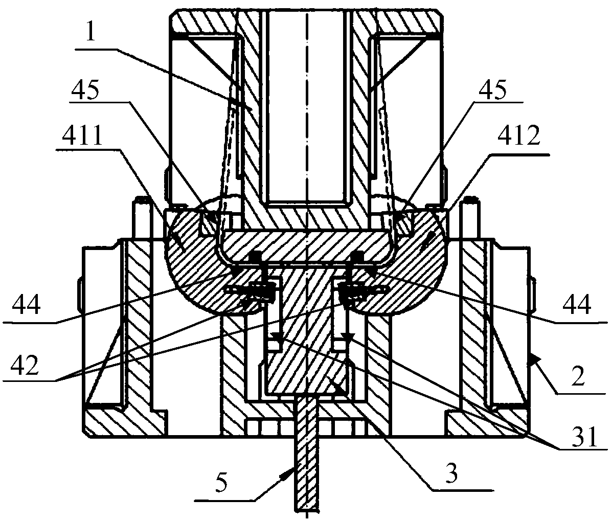
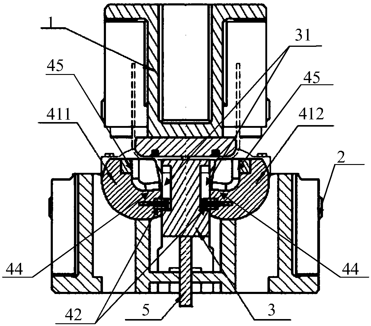
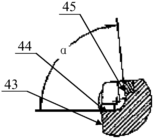
[0022] Such as figure 1 As shown, a novel stamping mold includes an upper mold 1, a lower mold base 2 and a lower mold installed in the lower mold base 2. The device and the left concave module 411 and the right concave module 412 that are symmetrically distributed on both sides of the ejector core 3 and are movably installed on the lower mold base 2 for angular rotation, the left concave module 411 and the right concave module 412 are facing the ejector core 3. One side on both sides is a concave module positioning surface 43, and the middle part of the concave module positioning surface 43 is symmetrically fixed with a positioning block 42, respectively. The elongated positioning groove 31 that moves up and down inside, the concave surface of the left concave module 411 and the right concave module 412 includes a supporting surface 44 adjacent to the concave module positioning surface 43 and a folding edge adjacent to the upper edge of the concave module. curved surface 45,...


PUM


Abstract

The invention relates to a novel punch forming mold. The mold comprises an upper mold, a lower mold base and a lower mold mounted in the lower mold base; the lower mold comprises a material ejecting core, a telescopic device mounted at the bottom of the material ejecting core, a left female mold block and a right female mold block, wherein the left female mold block and the right female mold block are symmetrically distributed on the two sides of the material ejecting core and movably mounted on the lower mold base to be subject to angular rotation; the faces, facing the two sides of the material ejecting core, of the left female mold block and the right female mold block are female mold block positioning faces, positioning blocks are symmetrically and fixedly mounted in the middles of the two female mold block positioning faces, long positioning grooves capable of enabling the positioning blocks to move vertically in are symmetrically formed in the upper ends of the two sides of the material ejecting core, and sinking faces of the two female mold blocks comprise bearing faces adjacent to the female mold block positioning faces and bending faces adjacent to the upper edges of the female mold blocks; when the upper mold is pressed to the lowest, the upper edge of the material ejecting core is flush with the bearing faces; the bottom face and the vertical face of a workpiece manufactured through the technical scheme can obtain the better perpendicularity.

Description

【Technical field】 [0001] The invention relates to the technical field of stamping, in particular to a novel stamping mold. 【Background technique】 [0002] The traditional stamping mold adopts the form of the fixed size of the upper punch and the lower die. This form of stamping mold has great disadvantages in the forming process of some workpieces. Because some workpiece materials have a certain amount of springback, the forming ends There is a large deviation between the verticality of the bottom surface of the rear workpiece and the vertical surface. 【Content of invention】 [0003] The purpose of the present invention is to provide a new type of stamping mold that can increase the forming capacity, aiming to solve the problem that some workpiece materials with springback have large deviations in the perpendicularity between the bottom surface of the workpiece and the vertical surface after forming. [0004] The present invention is achieved in the following way: a novel...

Claims


Application Information

Patent Timeline
Patent Type & Authority Patents(China)
IPC IPC(8): B21D37/10
CPCB21D37/10
Inventor 覃荣平
Owner 柳州市银翔机械有限责任公司
Why Eureka
Try Eureka