Vacuum boiling cutting removing device

A technology of vacuum boiling and vacuum generation, which is applied in the direction of dust removal, metal processing machinery parts, maintenance and safety accessories, etc., to achieve good chip removal effect, improve emission compliance rate, and increase service life.

Inactive Publication Date: 2017-02-22
DALIAN MODERN AUX MACHINERY DEV & MFG CO LTD
View PDF9 Cites 3 Cited by
  • Summary
  • Abstract
  • Description
  • Claims
  • Application Information

AI Technical Summary

Problems solved by technology

Therefore, once the cylinder block of the engine, the water jacket cavity of the cylinder head are particularly complicated or there is the above-mentioned special oil passage in the turbine shaft hole of the cylinder head, then there is nothing that can be done by conventional cleaning means.

Method used


Image

  • Vacuum boiling cutting removing device
  • Vacuum boiling cutting removing device
  • Vacuum boiling cutting removing device

Examples


Embodiment 1

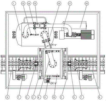
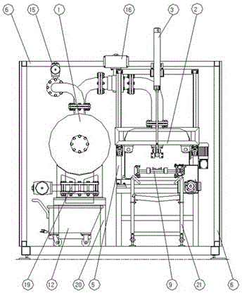
[0027] Such as Figure 1-Figure 6 The shown vacuum boiling chip removal device includes the workpiece 7 which is transported through the transmission mechanism and placed in the workpiece warehouse 10. The cavity of the workpiece warehouse 10 is a tunnel-type cavity formed by plate welding, and the two ports of the workpiece warehouse 10 are connected to the warehouse. The door sealing mechanism and the workpiece warehouse 10 are connected with a vacuum generating mechanism.

[0028] The vacuum generating mechanism includes a vacuum pump 18 connected to the sealed isolation tank 1 through the pipeline 17, and the sealed isolation tank 1 is connected to the workpiece warehouse 10 through the external pipeline 4 of the workpiece warehouse. The pipeline 4 is equipped with a workpiece warehouse air extraction automatic control valve 16 , and a workpiece warehouse air injection automatic control valve 24 is installed between the workpiece warehouse air extraction automatic control ...

Embodiment 2

[0039] The structural connections and working process of the vacuum boiling chip removal device in this embodiment are the same as those in Embodiment 1, and the different technical parameters are: during operation, the vacuum degree of the isolation tank 1 is set to 25 mbar.

Embodiment 3

[0041] The structural connections and working process of the vacuum boiling chip removal device in this embodiment are the same as those in Embodiment 1 and Embodiment 2, and the different technical parameters are: during operation, the vacuum degree of the isolation tank 1 is set to 50 mbar.


PUM


Abstract

The invention belongs to the technical field of machine tool accessories, and particularly relates to a vacuum boiling cutting removing device used for removing cuttings of automobile engine cylinders and cylinder heads. According to the vacuum boiling cutting removing device, workpieces are connected with a workpiece cabin through a conveying mechanism, two ports of the workpiece cabin are connected with cabin door sealing mechanisms, and the workpiece cabin is connected with a vacuum generating mechanism. The vacuum generating mechanism comprises a vacuum pump which is connected with a sealed isolation tank through a pipeline, the sealed isolation tank is connected with the workpiece cabin through a workpiece cabin external pipeline, the pipeline is provided with an isolation tank air-exhaust internally piloted valve, and the workpiece cabin external pipeline is provided with a workpiece cabin air-exhaust internally piloted valve. A workpiece cabin air-injection internally piloted valve is arranged between the workpiece cabin air-exhaust internally piloted valve and the workpiece cabin. The sealed isolation tank connected with the sealed workpiece cabin is vacuumized, thin and small substances in the workpiece cabin are separated from the workpieces in a water boiling mode through the pressure difference and gathered to a low-pressure generating point, and therefore the purposes of removing cuttings is achieved, and the cutting removing effect on poor-openness potions or dead corner portions is good.

Description

technical field [0001] The invention relates to the technical field of machine tool accessories, in particular to a vacuum boiling chip removal device for chip cleaning of automobile engine cylinder blocks and cylinder heads. Background technique [0002] At present, in the engine processing production line, the cleaning of residual chips after processing the cylinder block and cylinder head is a very important link, and it is a key factor affecting engine emission standards. During the production and processing of the cylinder block and cylinder head, most of the chips are washed away by coolant in the processing equipment, and then enter the special cleaning equipment for targeted cleaning. [0003] The application and development of cleaning technology has gradually exposed some problems that cannot be solved by water-based media cleaning machines. Problem 1: The cavity of the engine block and cylinder head water jacket is complex, most of which are closed cavities, and t...

Claims


Application Information

Patent Timeline
Patent Type & Authority Applications(China)
IPC IPC(8): B08B5/04B08B13/00B08B15/04B23Q11/00
CPCB08B5/04B08B13/00B08B15/04B23Q11/0046
Inventor 王海洋何广维郭月胡融冰
Owner DALIAN MODERN AUX MACHINERY DEV & MFG CO LTD
Why Eureka
Try Eureka