Buoyance switch for track field drainage

A buoyancy switch and track technology, applied in the agricultural field, can solve the problems of accelerating drought and wasting water resources, and achieve the effect of fast drainage

Active Publication Date: 2017-02-22
于光成
View PDF4 Cites 0 Cited by
  • Summary
  • Abstract
  • Description
  • Claims
  • Application Information

AI Technical Summary

Problems solved by technology

However, in dry weather, when irrigating, part of the irrigation water will also seep into the infiltration and drainage pipes, and then be discharged through the infiltration culverts and group drainage pipes, thereby wasting water resources and accelerating the drought.

Method used


Image

  • Buoyance switch for track field drainage
  • Buoyance switch for track field drainage
  • Buoyance switch for track field drainage

Examples


Embodiment 1

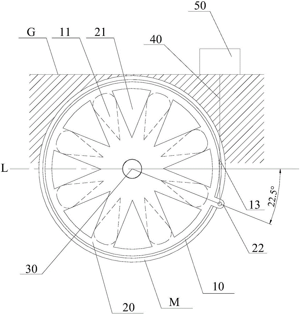
[0018] Buoyancy switch for drainage of track fields, such as figure 1 As shown, it includes an inner water retaining plate 10 and an outer water retaining plate 20. The inner water retaining plate 10 is fixed at the water outlet of the seepage and drainage waterlogging pipe M, and the outer periphery of the inner water retaining plate 10 is in interference fit with the inner wall of the seepage and drainage waterlogging water pipe M. Prevent water from flowing out between the inner water retaining plate 10 and the seepage and drainage waterlogging pipe M. The inner water retaining plate 10 is evenly distributed with eight inner water passing holes 11, and the eight inner water retaining holes 11 form a circular array; the outer water retaining plate 20 is connected with the inner water retaining plate 10 through a central axis 30, and the outer water retaining plate The plate 20 is close to the inner water retaining plate 10, and the outer water retaining plate 20 can rotate a...

Embodiment 2

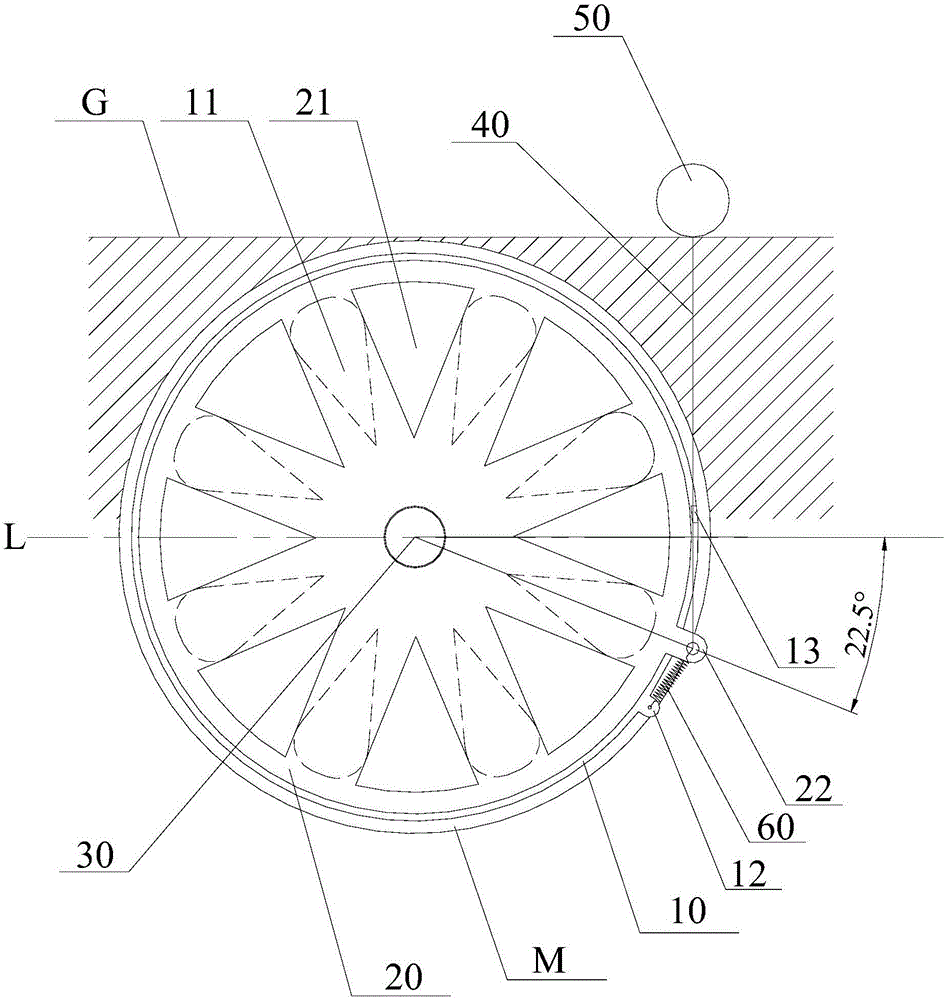
[0020] Buoyancy switch for drainage of track fields, such as figure 2 As shown, it includes an inner water retaining plate 10 and an outer water retaining plate 20. The inner water retaining plate 10 is fixed at the water outlet of the seepage and drainage waterlogging pipe M, and the outer periphery of the inner water retaining plate 10 is in interference fit with the inner wall of the seepage and drainage waterlogging water pipe M. Prevent water from flowing out between the inner water retaining plate 10 and the seepage and drainage waterlogging pipe M. The inner water retaining plate 10 is evenly distributed with eight inner water passing holes 11, and the eight inner water retaining holes 11 form a circular array; the outer water retaining plate 20 is connected with the inner water retaining plate 10 through a central axis 30, and the outer water retaining plate The plate 20 is close to the inner water retaining plate 10, and the outer water retaining plate 20 can rotate ...


PUM


Abstract

The buoyance switch for track field drainage comprises an inner water eliminator and an outer water eliminator. The inner water eliminator is fixed on a water outlet of a seepage drainage pipe. Eight inner water holes are evenly distributed on the inner water eliminator. Eight inner water holes are arranged in an annular array. The outer water eliminator is connected with the inner water eliminator through a central shaft. The outer water eliminator is capable of rotating around the central shaft. Eight outer water holes are evenly distributed on the outer water eliminator. Eight outer water holes are arranged in an annular array. The outer water holes and the inner water holes are on the same circumference. The outer water eliminator is provided with a first ear plate. A wire rope is fixed on the first ear plate. The other end of the wire rope is fixed with a floating block. In dry weather, no water is provided with the surface and the buoyance switch is off. Even if the irrigation water infiltrates in the seepage drainage pipe, the irrigation water can also be stored in the seepage drainage pipe, and then slowly seep into the soil to keep soil moisture for a long time. In flooding weather, the floating block drives the buoyance switch to open in time, so as to achieve the purpose of rapid drainage.

Description

technical field [0001] The invention belongs to the technical field of agriculture, and in particular relates to a buoyancy switch for track field drainage which is suitable for underground seepage and drainage systems of track fields. Background technique [0002] Track agriculture is a new type of ecological agriculture that creates a new era of agricultural production and automatic operation technology, agricultural production diversification and energy conservation and environmental protection. It aims to create a modern agricultural production technology that uses automated machinery to complete agricultural production tasks. At the same time of environmental protection, an ecological agricultural system with the whole industrial chain of agricultural production is formed. [0003] After heavy rains or floods, some water often accumulates in the farmland, which affects the growth of crops. In order to reduce the impact of floods on crops, it is necessary to drain the wa...

Claims


Application Information

Patent Timeline
IPC IPC(8): A01G25/09
CPCA01G25/09
Inventor 于林于光成
Owner 于光成
Why Eureka
Try Eureka