
Communication device with metal shell and NFC structure thereof

A metal shell and metal shell technology, applied in antenna equipment with additional functions, metal shells, transmission systems, etc., can solve problems such as reduced communication performance, and achieve the effects of uniform magnetic field, superior performance and cost saving

Active Publication Date: 2017-02-15
SHANGHAI DEMAN ELECTRONICS TECH
View PDF6 Cites 6 Cited by
  • Summary
  • Abstract
  • Description
  • Claims
  • Application Information

AI Technical Summary

Problems solved by technology

However, electromagnetic waves cannot radiate through the metal shell, which also makes it difficult for traditional NFC antennas to couple with external communication devices, and the communication performance is greatly reduced

Method used


Image

  • Communication device with metal shell and NFC structure thereof
  • Communication device with metal shell and NFC structure thereof
  • Communication device with metal shell and NFC structure thereof

Examples


Embodiment 1

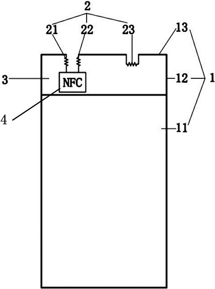
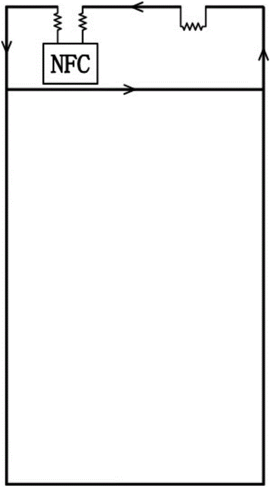
[0044] Such as figure 1 As shown, the NFC structure of the metal case provided by the present invention includes a metal case 1 , an inductance element 2 and an insulator; the metal case 1 includes a metal case body 11 , a side metal frame 12 and a top metal frame 13 . Between the top metal frame 13 and the metal shell body 11 is a plastic area 3 . The insulator is made of plastic material, forming a plastic area separating the metal shell body 11 and the top metal frame 13 . The inductance element 2 is an inductance with a high Q value. The surface of the metal shell body is complete without slots.

[0045] The inductance element 2 includes a first inductor 21 , a second inductor 22 and a third inductor 23 . There are two breakpoints on the top metal frame, which are divided into the first breakpoint and the second breakpoint. The two ends of the first breakpoint are respectively connected to one end of a first inductance 21 and one end of a second inductance 22; the othe...

Embodiment 2

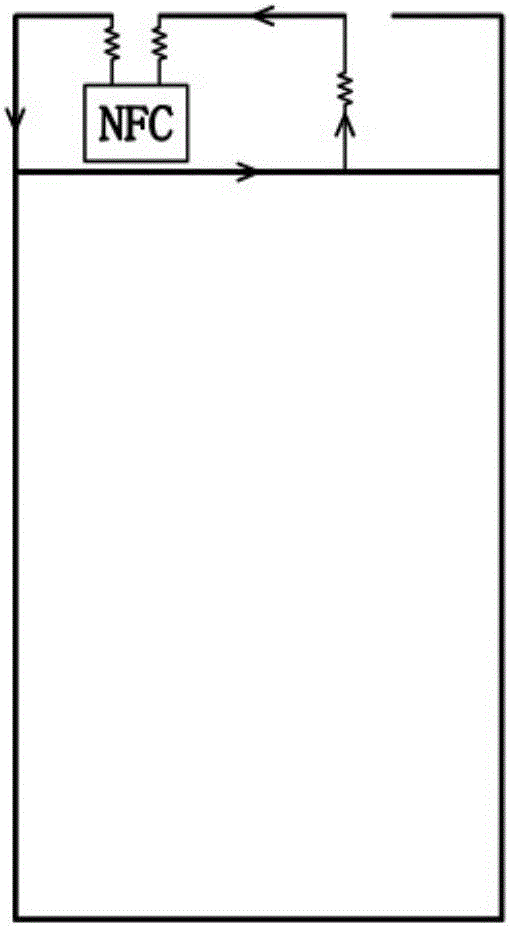
[0049] Such as image 3 , Figure 5 As shown, one end of the third inductor 23 connected to the top metal frame 13 is disconnected and connected to the metal shell body 11, or as Figure 4 As shown, the end of the first inductor 21 connected to the top metal frame 13 is disconnected and connected to the metal shell body 11 to obtain three NFC structures of the present invention with different loops and different radiation areas. This series of NFC structure is suitable for the connection position or method of the inductive element that cannot satisfy such figure 1 Communication equipment under conditions.

Embodiment 3

[0051] Such as Figure 6As shown, the NFC structure can directly connect the part between the first breakpoint and the second breakpoint of the top metal frame 13 to the inductive element 2 when there is no condition to use the metal frame 12 on both sides and the metal shell body 11 to radiate. Connect with NFC radio frequency circuit. The radiation area in this embodiment is composed of the top metal frame 13 , the inductance element 2 and the wires connecting the top metal frame 13 and the inductance element 2 , the inductance element 2 and the NFC radio frequency circuit.


PUM


Abstract

The invention provides a communication device with a metal shell and an NFC structure thereof. The communication device is composed of a metal shell and a plurality of inductance elements. The metal shell of the communication device consists of a top metal frame, a side metal frame and a metal shell body. A plastic region is formed between the top metal frame and the metal shell body; and two breaking points are arranged on the top metal frame. On the one hand, the inductance elements can be connected to the breaking points of the top metal frame to form a closed loop; and on the other hand, because of the low-pass and high-resistance characteristics, the mutual influence between the NFC and a radio frequency antenna is avoided. The communication device has the following advantages: no NFC antenna and ferrite are needed, so that the space is saved and the cost is lowered; the design is simple without any slotting processing, so that the product appearance is not damaged; because of the series inductance units in the loop, the mutual influence between the NFC and the radio frequency antenna is avoided; and radiation is realized by using the metal shell, so that the magnetic field is uniform and the performance is excellent.

Description

technical field [0001] The present invention relates to an NFC antenna, in particular to an NFC structure suitable for a near-field communication device with a metal shell structure and the communication device, in particular to an FPC-free (Flexible Printed Circuit Board) based on a metal back shell ) NFC structure of the antenna. Background technique [0002] Undoubtedly, in recent years, NFC (Near Field Communication) near-field communication technology has been more and more widely used in electronic products. [0003] The way traditional electronic products are equipped with NFC antennas is to attach the antennas inside the plastic case. The process requirements of this mounting method are simple, and since the plastic shell will not interfere or shield the electromagnetic radiation of the NFC antenna, the NFC performance is often relatively good. [0004] However, as people's requirements for the appearance and structure of electronic products are getting higher and ...

Claims


Application Information

Patent Timeline
Patent Type & Authority Applications(China)
IPC IPC(8): H01Q1/44H01Q1/24H01Q1/52H04B5/00H05K5/04
CPCH01Q1/241H01Q1/44H01Q1/521H04B5/00H05K5/04
Inventor 潘英鹤马超陈佳南黎鹏
Owner SHANGHAI DEMAN ELECTRONICS TECH
Learn More