
Painting mixing apparatus for painting manufacturing

A control device and paint mixing technology, applied in control/adjustment systems, multiple fluid ratio control, ratio control, etc., can solve the problems of low efficiency, labor-intensive, inability to deploy paints for lacquer painters, etc., and achieve enhanced The effect of deployment, improving deployment efficiency and saving manpower

Inactive Publication Date: 2017-02-15
哈尔滨漆艺之星科技发展有限公司
View PDF0 Cites 0 Cited by
  • Summary
  • Abstract
  • Description
  • Claims
  • Application Information

AI Technical Summary

Problems solved by technology

[0002] In the process of making lacquer paintings, in many cases, the existing color paints cannot meet the needs of lacquer painting producers, which requires the paint to be adjusted according to the needs of lacquer painting producers. The general method of mixing paint is, according to the pigment principle, And according to the experience of lacquer painting makers, paints of different colors are placed inside the mixing drum, and manually stirred and blended. There are fewer ingredients, and it is impossible to deploy the color paint required by the lacquer painting maker, and the manual mixing and deployment is labor-intensive and inefficient

Method used


Image

  • Painting mixing apparatus for painting manufacturing

Examples


Embodiment 1

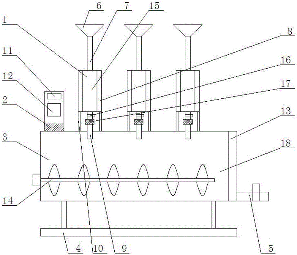
[0016] like figure 1 As shown, a paint mixing device for lacquer painting production includes a feeding device 1, a control device 2, a blending device 3, a support seat 4, and a discharge pipe 5. The top of the device 3 and the right end of the control device 2 are equipped with three feeding devices 1, the right side of the blending device 3 is equipped with a discharge pipe 5, and the bottom end of the blending device 3 is equipped with a support seat 4; Material pipe 7, transfer storage box 8, feed pipe 9, support frame 10, the lower end of the feed hopper 6 is connected to the transfer storage box 8 through the feed pipe 7, and the bottom end of the transfer storage box 8 passes through the support frame The device 10 is at the upper end of the blending device 3, and the middle of the bottom end of the transfer storage box 8 is connected to the blending device 3 through the feed pipe 9; the control device 2 is connected to control the feeding device 1 and the blending dev...

Embodiment 2

[0018] like figure 1 As shown, the transparent observation window 15 is installed on the front side of the transfer storage bin 8 .

Embodiment 3

[0020] like figure 1 As shown, an electric control valve 16 and a flow meter 17 are installed on the feed pipe 9 from top to bottom; the electric control valve 16 and flow meter 17 are all connected to the control device 2 .


PUM


Abstract

The invention discloses a painting mixing apparatus for painting manufacturing. The painting mixing apparatus includes feed apparatuses, a control apparatus, a mixing apparatus, a supporting pedestal, and a discharging pipe. The left side of the top end of the mixing apparatus is provided with the control apparatus. The top end of the mixing apparatus and the right end of the control apparatus are provided with three feed apparatuses. The right side of the mixing apparatus is provided with a discharging pipe. The bottom end of the mixing apparatus is provided with the supporting pedestal. Each feed apparatus is composed of a feed hopper, a feed pipe, a transfer storage case, a supply pipe, and a supporting rack. The lower end of the feed hopper is connected to the transfer storage case through the feed pipe. The bottom end of the transfer storage case is arranged at the upper end of the mixing apparatus through the supporting rack. The middle of the bottom end of the transfer storage case is connected to the mixing apparatus through the supply pipe. The mixing apparatus is composed of a mixing case and a power-driven stirring apparatus. According to the invention, the apparatus herein can accurately control the amount of every pigment to be added, real-time record the ratio of pigments to be mixed, and is easy for next use. The apparatus herein, by adopting the power-driven stirring apparatus, facilitates mixing, saves labor, and increases mixing efficiency and mixing effects.

Description

technical field [0001] The invention relates to the field of lacquer painting production tools, in particular to a paint mixing device for lacquer painting production. Background technique [0002] In the process of making lacquer paintings, in many cases, the existing color paints cannot meet the needs of lacquer painting producers, which requires the paint to be adjusted according to the needs of lacquer painting producers. The general method of mixing paint is, according to the pigment principle, And according to the experience of lacquer painting makers, paints of different colors are placed inside the mixing drum, and manually stirred and blended. There are fewer ingredients in the paint, and the color paint required by the lacquer painting maker cannot be deployed, and the manual stirring and deployment is labor-intensive and inefficient. Contents of the invention [0003] The purpose of the present invention is to provide a paint mixing device for lacquer painting ...

Claims


Application Information

Patent Timeline
Patent Type & Authority Applications(China)
IPC IPC(8): G05D11/13
CPCG05D11/132
Inventor 白艳萍
Owner 哈尔滨漆艺之星科技发展有限公司
Learn More